
Loading...
Loading...
Loading...
Loading...
Loading...
Loading...
Loading...
Loading...
Loading...
Loading...
Loading...
Loading...
Loading...
Loading...
Loading...
Loading...
Loading...
Loading...
Loading...
Loading...
Loading...
Loading...
Loading...
Loading...
Loading...
Loading...
Loading...
Loading...
Loading...
Loading...
Loading...
Loading...
Loading...
Loading...
Loading...
Loading...
Loading...
Loading...
Loading...
Loading...
Loading...
Loading...
Loading...
Thank you for purchasing the Miltech Simulations MH60, in partnership with Blackbird Simulations.
At Miltech Simulations, we remain committed to pushing the boundaries of what’s possible in Microsoft Flight Simulator. Following the success of our CH47D and other military platforms, we now present our most advanced rotary-wing project to date: the legendary MH60, brought to life after over a year of intensive development.
The Miltech Simulations MH60 is a multi-role, maritime helicopter capable of performing a wide variety of missions, from anti-submarine warfare and search-and-rescue, to medevac and special operations support. With advanced mission systems, modular configurations, and a highly detailed 3D model, the MH60 delivers a new level of features depth and realism to the sim.
This product is the result of a close collaboration with Blackbird Simulations, a renowned name in the flight simulation industry. Combining Blackbird’s world-class visual modeling with our own expertise in systems programming and mission integration, the MH60 sets a new standard for helicopter simulation.
We are proud to share this ambitious project with the community, and we hope it becomes a core part of your sim experience.
Miltech Simulations & Blackbird Simulations.
Manual Page to be Expanded. Please check again in 24hrs.
As usual in recent Miltech Simulations releases, we include 4 detailed mini-sceneries with the aircraft, each tailored for mission-oriented operations:
KLDR – San Diego Coast Guard Air Station (USA) A busy USCG facility located along the San Diego waterfront, supporting maritime patrol, SAR, and border operations.
LEPM - Peñón de Vélez de la Gomera Helipad (Spain) A remote outpost on the Mediterranean coast, suited for Strait of Gibraltar patrols, anti-submarine warfare missions, and confined landing practice with the MH-60R.
KCGK – Kodiak Coast Guard Air Station (USA) One of the largest Coast Guard bases in the United States, situated in the rugged terrain of Kodiak Island, Alaska, and home to long-range SAR and patrol missions.
YGAD – Garden Island Naval Base (Australia) A key Royal Australian Navy installation near Perth, optimized for MH60R operations, including ASW, training, and fleet support.
All these locations feature helipads (for Ready to Fly start) and "Parking Spots" (for Cold and Dark Start).
In partnership with Blackbird Simulations
SIMULATION USE ONLY - DO NOT USE THIS DOCUMENTATION ON A REAL AIRCRAFT
An active internet connection is required on initial activation of the aircraft.
Blade Fold Disabled Temporarily
Due to several bugs affecting the Blade Fold feature, we’ve decided to temporarily disable it for the initial release and postpone its availability to a future update.
At Miltech Simulations, we continue innovating. Following the success of our previous releases, we now present the result of over a year of development on one of the most versatile military helicopters ever built. The MH60 is ready for deployment in Microsoft Flight Simulator, in partnership with Blackbird Simulations.
Miltech Simulations MH60 is a multi-mission maritime helicopter, capable of executing complex operations such as anti-submarine warfare, search and rescue, medevac, and special operations. Its powerful engines, rugged airframe, and advanced avionics make it a dependable platform for even the most demanding scenarios. Designed with precision and realism in mind, the MH60 brings authentic mission capabilities to the virtual skies.
We've put together some helpful guides for you to get set up with our product quickly and easily.
An active internet connection is required on initial activation of the aircraft.
After this, the aircraft can be used offline for a period of time. Our system will automatically check your license sporadically.
If you require assistance or have a setup that prevents this from functioning correctly, please contact us at [email protected]
Miltech Simulations’ MH-60 uses a lightweight activation and version control system to ensure your product license is valid and always up to date.
A Low VRAM Version is available for users with limited hardware, particularly GPUs with 8GBs or less VRAM. If you are experiencing low FPS, it is most likely attributed to this.
Just unzip directly onto your community folder. Replace all files.
Low VRAM total Reduction is aprox. 2.5GB, at moderate visual impact.
MiltechSimulations.com / Contrail App A serial key is generated and automatically entered into the product. Under normal circumstances, activation happens silently and without user input.
iniBuilds / BlackbirdSim.com A serial key is provided at the time of purchase. You must copy and paste this key into the aircraft’s PFD Popup activation panel upon first simulator load.
MS Marketplace No activation key is required. The product activates automatically through the simulator platform.
If the product fails to activate correctly, it may present in one or more of the following ways:
Primary Flight Display (PFD) and Multi-Function Display (MFD) appear completely black
Error messages appear on one or both avionics screens upon loading the aircraft
Activation prompt fails to accept a valid key or does not respond
If you experience any of these issues, please contact our support team with your purchase information and a brief description of the problem. We're here to help.
A Low VRAM Version is available for users with limited hardware, particularly GPUs with 8GBs or less VRAM. If you are experiencing low FPS, it is most likely attributed to this.
Just unzip directly onto your community folder. Replace all files.
Low VRAM total Reduction is aprox. 2GB, at low visual impact.
An ultra-low VRAM version is available for users with GPUs with 6GBs or less VRAM.
Just unzip directly onto your community folder. Replace all files.
Ultra Low VRAM total reduction is aprox. 3.5 GB at moderate visual impact.
CPU: Quad-core processor or better.
GPU: At least 6GB of dedicated memory, Nvidia 1060 or better.
RAM: 8GB Minimum.
Hard Disk: At least 4GB Recommended.
Click on "Downloads". Your products will download and install automatically.'
Click “Install” and wait for the product to install successfully.
All support for this product will be handled initially by Miltech Simulations. Support is available via our support forum: https://miltechsimulations.talkyard.net/latest
Our support is also offered via email in a 1-to-1 manner, through our Email Address: [email protected]
For company/business inquiries, please contact [email protected]

This page only applies to MH60 Romeo.
The Acoustic and ASW System on the MH60R enables detection, localization, and engagement of submerged submarines using a suite of deployable and onboard sensors. It utilizes sonobuoys and/or sonodippers to receive acoustic data.
A sonobuoy is a small, expendable sonar system dropped into the ocean from an aircraft or helicopter. Once in the water, it transmits acoustic data back to the aircraft for submarine detection and tracking. They can be Passive (e.g., DIFAR): Listens for noise from submarines (e.g., propellers, engines) or Active (e.g., DICASS): Emits pings and listens for echoes to determine range and bearing. For the terms of MSFS Simulation, either way is identical.
Sonobuoys as modeled in MSFS have a limited transmitting range, and duration of approximately 5 minutes. Few seconds after releasing, the sonobuoy will begin transmitting data to the aircraft on the MD
Sonobuoys will remain floating on the surface of the water, and their position is visible from the air as a yellow buoy.
A Sonodipper is a nickname for the MH-60R’s retractable, active dipping sonar system, officially known as the AN/AQS-22 ALFS (Airborne Low-Frequency Sonar). It consists of a large sonar dome that is lowered into the water by winch when the helicopter hovers. Unlike sonobuoys, which are expendable and left behind, the Sonodipper is a reusable system that provides real-time active sonar data, including precise range and bearing information on submerged targets.
Sonodippers shall remain underwater to receive any data from nearby submarines. This can sometimes be inconvenient as the pilot shall fly very close to the water.
Use the pilot's side Keyset, under WPNS page to load/unload sonobuoys. This will get you a full load of 25 buoys to release.
To release, turn on the MASTER ARM switch on the Armament Control-Indicator (ACI) panel, then press the BUOY LAUNCH button. This will deploy one sonobuoy from the left side of the helicopter.
Use the pilot's side Keyset, under WPNS page, to load/unload sonodipper. Sonodipper will be visible as soon as loaded, it is recommended to do this as you are flying over water.
Sonodipper does not require arming or releasing. It will begin transmitting as soon as the aircraft is flying above water, and sonodipper is under water.
Please note that ACST Pages will only fuction as depicted with Miltech Mission Hub, and when using compatible mission modes (Submarine Attack, Submarine Intercept). More information:
Use the ACST Button on the Mission Display to open the Acoustics page. Use PG UP and PG DN buttons on the right side bezel to alternate between Sonobuoy and Sonodipper.
We recommend using the Copilot MD for Acoustics, as this display is replicated on the ASW Console in the cabin.
Up to four Sonobuoy instances can be displayed simultaneously. Releasing multiple buoys increases the accuracy of target localization. The vertical axis on the display represents the bearing to the detected source, in degrees, while the horizontal axis shows the distance, in yards.
Target returns typically appear as dark spots on the display. Sonobuoys are relatively cheap and expendable sensors, which means their acoustic returns often include a significant amount of background noise or interference, and have a limited range.
The Sonodipper is a more advanced and precise system compared to sonobuoys, offering greater range and accuracy. Like sonobuoys, it presents contact information on a two-dimensional axis, with bearing to the target on the vertical axis and distance in yards on the horizontal axis. The Sonodipper can accurately determine both range and bearing to a contact, which appears as a green dot on the display. Additionally, the Hydrophone Scope shows the current depth of the sonar transducer below the water surface.
Navigate to the NAV Menu, and select SRCH PTTR option. This will open up the SEARCH PATTERN Pop-up menu on the Mission Display.
Use the PG UP or PG DN keys, either on the Keyset or MD Bezel, to move the cursor. Press ACK to select a Search Pattern. The FTP Flightplan will now be overwritten with the selected Search Pattern.
You may now close the Pop-up by pressing SRCH *PTTR*. Adjust Map Range as desired and fly the Search Pattern manually.
All Search Patterns are predefined and non-editable. They all originate from the aircraft location at the time of activation.
SIERRA SIERRA: Expanding Square
Sierra Sierra 10L (10 Legs)
Sierra Sierra 15L (15 Legs)
The search area is small,
Weight on Wheels Indicator: Displays whether the helicopter is on the ground (weight on wheels detected) or airborne.
Misc. Sling Load Information: Displays sling load status such as distance to load, bearing to load, attachment status, or release readiness. Only active during sling load operations.
HELO/BASE Indicator: Shows whether the information is currently centered on the HELO (your aircraft) or on the BASE (your assigned landing/recovery station). Matches the state of the STN/HELO Selector.
HELO/BASE Coordinates and information: Displays coordinates, elevation, and/or bearing/range to the HELO or BASE, depending on selection. Useful for return-to-base navigation, offset planning, or SAR station keeping.
Warnings and Cautions: Critical messages alerting the pilot to system malfunctions or safety-related issues. These are highlighted prominently, often requiring acknowledgment.
Warnings display in RED, and indicate conditions that require immediate crew awareness and corrective action. These messages represent serious system malfunctions or flight conditions that may compromise safety if not promptly addressed.
Cautions are displayed in YELLOW and signify conditions that require attention but are not immediately hazardous. They typically indicate a system anomaly, configuration issue, or limitation that the crew should monitor and correct as soon as practical.
Advisories: Non-critical messages providing status updates, configuration reminders, or informational system notifications.
Radio Frequencies: Shows current active and standby frequencies for the aircraft’s radios. Displays latest frequency entered on the TUNE Page. For example, if the latest frequency entered is COMM2, it will display R (radio), followed by the frequency, followed by C2. If the latest frequency inputted is an ADF1 Station, displays as R(Frequency)A1
Transponder Code: Displays the current squawk code (Transponder ID, also known as IFF Code)
HELO/BASE Switch Pushbutton: Allows quick toggling between HELO and BASE information focus.
The DIAG (Diagnostic) Page provides access to system diagnostic and maintenance-related submenus. These pages are primarily intended for ground support personnel and system monitoring, offering insight into subsystem performance and configuration data.
Purpose
The DIAG Page is designed to display diagnostic information, system status summaries, and built-in test (BIT) results for various aircraft systems. It serves as a maintenance and troubleshooting interface within the avionics suite.
However, in this simulation, the DIAG Page and its associated submenus are not fully modeled. They are included for display and reference purposes only and do not provide active system interaction or live diagnostic functionality.
Manual Page to be Expanded. Please check again in 24hrs.
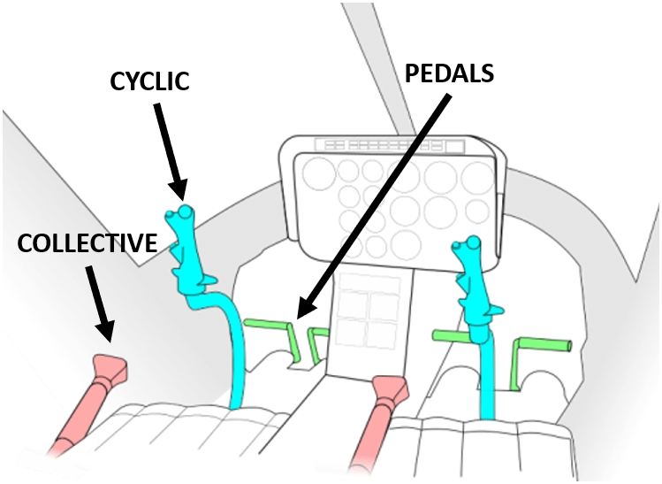
Pilot’s Cyclic: Primary flight control used to command pitch and roll by tilting the rotor disc. Controls forward, aft, and lateral movement of the aircraft.
Copilot’s Cyclic: Primary flight control used to command pitch and roll by tilting the rotor disc. Controls forward, aft, and lateral movement of the aircraft.
Pilots’ Collective
Blade Fold Disabled Temporarily
Due to several bugs affecting the Blade Fold feature, we’ve decided to temporarily disable it for the initial release and postpone its availability to a future update.
Blade Fold/Unfold is an FS24-Only feature. Tail fold is available on both FS20 and 24.
The MAP Page provides the crew with a full-color, moving-map display that enhances situational awareness by integrating navigational data, aircraft position, and nearby traffic or terrain features. It serves as the primary tactical and navigation reference within the avionics suite.
Overview
The MAP Page displays a real-time geographic representation of the helicopter’s current position and surrounding environment. It integrates multiple data layers, including:
ACST Page Button
PG UP Button: Alternate between Sonobuoy and Sonodipper pages.
PG DN Button: Alternate between Sonobuoy and Sonodipper pages.
The MH60’s communication system is equipped with dual radios, allowing independent operation of COMM 1 and COMM 2 channels. In the current MSFS implementation, the system is limited to supporting only standard VHF/UHF COMM frequencies as defined by the simulator. This means the radios cannot tune to NAV, HF, or encrypted channels.
The COMM Radios are operated with the Keyset, via the TUNE and COMM menu/popup. For more information omn the keyset, refer to


The location of the search object is known within relatively close limits, but some doubt exists about the distress position, and
A concentrated search is desired
VICTOR SIERRA: Sector Search
Victor Sierra 5NM (5 Nautical Miles per Leg)
Victor Sierra 10NM (10 Nautical Miles per Leg)
The search area is small,
The location of the search object is well known, and
A concentrated search is desired.
CHARLIE SIERRA: Creeping Line Search
Charlie Sierra 1NM (1 Nautical Mile spacing between Legs)
The search area is large,
The location of the search object is approximate, but there is a greater chance that the search object is at one end of the search area versus the other (i.e. debris was found on one end during a previous search), and
Uniform coverage is desired.
PAPA SIERRA: Parallel Search
Papa Sierra 1NM (1 Nautical Mile spacing between Legs)
The search area is large,
The location of the search object is approximate, and
Uniform coverage is desired.

Pilots’ Antitorque Pedals: Control the pitch of the tail rotor blades to manage yaw (nose direction) and counteract main rotor torque.
Pilot Primary Display: Digital flight display showing attitude, airspeed, altitude, heading, vertical speed, and navigation symbology. More information Primary Display (PD)
Pilot Mission/Multifunction Display: Displays various mission elements such as Maps, FLIR, Sensor Integration, WCA, etc. More Information Mission/Multi-Function Display (MFD)
Copilot Mission Display: Digital flight display showing attitude, airspeed, altitude, heading, vertical speed, and navigation symbology. More information Primary Display (PD)
Copilot Primary Display: Displays various mission elements such as Maps, FLIR, Sensor Integration, WCA, etc. More Information Mission/Multi-Function Display (MFD)
Chronometer: Provides digital timekeeping for mission timing, navigation, etc.
Radar Warning Receiver (RWR): Not Modeled
Standby Instruments: Airspeed Indicator, Attitude Director Indicator, Altimeter, Stabilator Indicator.
Standby Compass: Magnetic compass used as a backup heading reference.
Warning and Caution Lights: Master Warning, Master Caution, Rotor RPM, etc.


A YELLOW background with black text identifies a caution message that has not yet been acknowledged. This visual distinction helps the crew quickly identify new or pending cautions.
To acknowledge a caution, the crew must press the Master Caution button located on the glareshield. Once pressed, the background color reverts to standard yellow text on a black background, confirming that the caution has been acknowledged.
FUEL QTY LOW Caution indicates fuel is under BINGO quantity. The HELO/BASE indicator automatically switches to BASE, displaying the heading and bearing to the base. Upon this caution, the pilot shall take immediate action to return to the base, or land at a suitable place.


Pilot's Side Keyset: The Keyset is the primary interface used to interact with the Communication, Navigation, Mission and Weapons Management Systems onboard the MH60. It also provides submenus to configure the aircraft's cabin layout, equipment loadout, and other mission-specific settings. For more information, Keyset
Copilot's Side Keyset: Temporarily disabled for input for performance considerations.
Autopilot System Control Panel: Controls the Autopilot System, Stability Augmentation System and related systems. For more information, Automatic Flight Control System (AFCS) and Stability Augmentation System (SAS)
Airborne Mine Counter Measures (AMCM) Coupler Panel: Not modeled.
Stabilator Control Panel: Provides power and manual command to the automatic Stabilator System.
Armament Control-Indication (ACI) Panel: Energizes the Armament control panel, provides a clickable input to deploy sonobuoys (MH60R). More information
Miscellaneous Switch Panel: Hosts controls for auxiliary systems, including the Backup Hydraulic Pump, Tail Servo ON/OFF, and Gust Lock engagement.
Pylon Jettison Panel: Provides emergency jettison capability for external weapon pylons or stores. Jettison can be done individually by pylon selected. More information
Environmental Control System: Controls cabin heating, ventilation, and cooling functions. For display purposes only.
IHADSS (Integrated Helmet and Display Sight System): Visor is currently not modeled in MSFS. A visor prototype is under R&D.
Control Monitor Panel: Provides power to the computers and EGI/INS-GPS System of the aircraft
Blade Fold Panel: Manages the operation of the blade fold and tail fold mechanisms for shipboard storage. More information: Tail and Rotor Fold/Unfold Operations
Blade De-Ice Panel: Controls the rotor blade anti-ice system.
Operator Control Panel: Enables control of volume of different communication channels.
Backup Radio Control Unit: Provides redundant communication capability in case of failure of the primary radio systems.
Fuel Management Control Panel: Displays fuel levels and controls fuel transfer between tanks. Supports management of auxiliary tanks, fuel balancing, and refueling operations. More information:
Tail Wheel Lock: Locks the tail wheel in place for ground handling stability. Unlocks for taxi and maneuvering as needed.
Parking Brake Lever: Engages the Parking Brake.
The MH60 features a folding tail boom, allowing the aircraft to reduce its footprint for shipboard or hangar storage. This function is fully animated and can be controlled via in-cockpit switches.
Ensure the aircraft is on the ground with the engines off.
Set Parking Brake.
On Pilot's Side Keyset, [CONFIG] Page, press TAIL FOLD. The option is crossed out if conditions are not met.
The tail folding sequence will start automatically. Once completed, the keyset option changes to TAIL *UNFLD*
To unfold, press the TAIL *UNFLD* button. The sequence starts automatically until the surfaces are unfolded and locked in place.
The MH60's main rotor blades can be folded for compact storage. This system is independent of tail folding and does not necessarily require the tail to be folded.
Ensure the aircraft is on the ground with the engines off.
Set Parking Brake.
Engage Master Blade Fold switch, located in the aft section of the centre console, on the Copilot Side, Blade Fold Panel.
Use the Blade Fold Switch to fold/spread the rotors.
Moving the switch from OFF to FOLD energizes the system and starts the Blade Folding sequence. The Status lights will indicate the status and position of the blades.
Moving the switch from OFF to SPREAD energizes the system and starts the Blade Unfolding sequence. The Status lighs "FLIGHT" and "SPREAD" indicate the rotors are extended and locked for engine start.
Navaids (VORs, NDBs, TACANs, waypoints, and fixes)
Flight plan route and waypoints
Terrain and elevation shading
Airports and navigation facilities
The page automatically updates as the aircraft moves, keeping the helicopter symbol centered or track-oriented depending on the selected mode.
Display Features
Full-Color Map Rendering: The background map is rendered in full color, with terrain, coastlines, and airspace boundaries clearly distinguished for easy interpretation.
Orientation Modes: The orientation mode can be selected using the N/H/T Button located on the Primary Display (#16 on this diagram) Primary Display (PD)
Heading Up: The map rotates to match the aircraft’s current heading.
North Up: The map remains north-oriented while the aircraft symbol rotates according to heading.
Zoom Levels: Adjustable range scales allow the crew to select the desired map range for enroute or terminal operations. Zoom can be adjusted with the PG UP and PG DN buttons, located both on the bezel of the MFD (#5 and #6 on this diagram ) or on the Keyset Keyboard.
The PLAN and TACT Pages provide simplified, high-contrast navigation and tactical displays designed for mission planning, route verification, and tactical situational awareness. Both PLAN and TACT Pages present the same symbology and flight information found on the MAP Page—such as waypoints, flight plan legs, airspaces, and navaids—but are displayed on a solid green background rather than a full-color map. As such, these do not display any terrain or elevation shading.
Instrument Return Information
Please read Acoustic and Antisubmarine Operations
Please note that ACST Pages will only fuction as depicted with Miltech Mission Hub, and when using compatible mission modes (Submarine Attack, Submarine Intercept). More information: Mission Procedures
Use the ACST Button on the Mission Display to open the Acoustics page. Use PG UP and PG DN buttons on the right side bezel to alternate between Sonobuoy and Sonodipper.
We recommend using the Copilot MD for Acoustics, as this display is replicated on the ASW Console in the cabin.
Up to four Sonobuoy instances can be displayed simultaneously. Releasing multiple buoys increases the accuracy of target localization. The vertical axis on the display represents the bearing to the detected source, in degrees, while the horizontal axis shows the distance, in yards.
Target returns typically appear as dark spots on the display. Sonobuoys are relatively cheap and expendable sensors, which means their acoustic returns often include a significant amount of background noise or interference, and have a limited range.
The Sonodipper is a more advanced and precise system compared to sonobuoys, offering greater range and accuracy. Like sonobuoys, it presents contact information on a two-dimensional axis, with bearing to the target on the vertical axis and distance in yards on the horizontal axis. The Sonodipper can accurately determine both range and bearing to a contact, which appears as a green dot on the display. Additionally, the Hydrophone Scope shows the current depth of the sonar transducer below the water surface.

Use PG UP or PG DN, either on the Keyset or MD Bezel, to select a radio to tune. Remember, anytime you see a white box highlighted WHITE, it is a cursor that may be interacted with PG UP/DN/LEFT/RIGHT.
Once selected, press ACK or SEL (MD Bezel or Keyset) to enter a frequency.
The STBY FREQ will now appear with a green background, indicating that the field is now active and ready to receive input.
Use the Keyset numberpad to enter frequency. The decimal period is added automatically.
Once completed, press ACK again to validate and change frequency. If the entered frequency is invalid, frequency will not be changed.
Alternatively, you may press ENT to directly validate the frequency and XFER to Active. You may also use ENT at any time while the TUNE Pop-up is open to XFER the frequencies selected.
A minimum 2% Deadzone in Collective and Pedal (In some cases up to 5% on old or inaccurate hardware) is required for AFCS to function correctly. Not enough deadzone will result in the input controllers and the system inputs conflicting with each other, leading to erratic or unexpected behavior. No deadzone is required on Cyclic, fully supporting unsprung cyclics.
If you are not familiar with helicopters, this guide should help you understand the basic controls that make them fly, and help you configure the controls correctly.
The Cyclic: This stick sits between your legs. Moving it forward or back controls the helicopter's pitch (nose up or down). Moving it side-to-side controls the helicopter's roll (leaning left or right).
Pitch Binding: ELEVATOR AXIS or CYCLIC LONGITUDINAL AXIS
Roll Binding: AILERONS AXIS or CYCLIC LATERAL AXIS
Rotor Brake: Hydraulic system used to stop or slow the main rotor blades after engine shutdown. Rotor brake Binding: ROTOR BRAKE
The design of the MH60 makes it an inherently stable aircraft. No pedal input is required to keep the aircraft under control. For this reason, Control Sensibility is a personal preference of the user and we don't have any particular recommendations to make.
Xbox Controller users may benefit from dampened sensibility in the cyclic axis for more precise control in hover.
A growing number of functions will be supported for Keybinding and Hardware Interaction over the upcoming updates. The Keybind Guide is frequently updated, and available here:
Engine Power Control Levers 1/2: OFF, IDLE, FLY. Also equipped with their corresponding starter buttons.
Fuel Control Levers 1/2: OFF, DIR, XFED. Determines from which tank does fuel feed into the engines. More information Fuel System
Anti-Ice and De-Ice System Panel: Controls the activation of engine inlet anti-ice, pitot tube heat, and blade de-icing systems.
Console and Instrument Lights Panel: Adjusts the brightness of cockpit console and instrument panel lighting.
Engine Ignition Switch: Enables or disables ignition circuitry for engine start.
Windshield Wipers: Controls the speed and activation of the pilot and copilot windshield wipers for visibility in rain or wet conditions.
Cargo Hook Panel: Controls the status of the hook and external cargo hook system. More information,
Utility Hyd Pump: Activates the utility hydraulic pump, which powers non-primary systems.
Rescue Hoist Panel: Controls the rescue hoist system for Search, Rescue and recovery operations. More information
Electrical System Panel: Provides control of the aircraft’s electrical power sources and distribution. Includes generator switches, battery, etc. For more information,
Fire Test Knob: Used to test the fire detection and warning systems for the engines and APU.
APU Control Switches: Starts, stops, and controls the Auxiliary Power Unit, which provides electrical and pneumatic power for ground operations.
Interior Lighting Panel, Formation Lights Knob: Controls cockpit glareshield lights, console lamps, and copilot instruments lighting. The formation lights knob adjusts brightness of external low-visibility lighting used during formation flight.
Exterior Lighting Panel: Controls aircraft position lights, anti-collision lights, landing/search lights, and other external lighting for ground and flight operations.
The WCA Page is divided into two main sections:
Message Display Area (center)
System Parameters Area (upper right corner)
1. System Parameters Area (Upper Right Corner)
The upper right corner of the WCA Page continuously displays the following essential engine and transmission parameters for quick reference:
XMSN TEMP (T): Transmission oil temperature.
XMSN PRESS (P): Transmission oil pressure.
ENG OIL TEMP: Engine oil temperature (for both engines).
ENG OIL PRESS: Engine oil pressure (for both engines).
NG: Gas generator speed (%).
These parameters are presented in a column format with color-coded limits (green for normal operation, yellow for caution range, and red for limit exceedance).
2. Message Display Area
The main area of the WCA Page presents system alerts and advisories. Unlike a simple text list, these messages are arranged in a format that mirrors the helicopter’s system layout, helping the crew quickly identify the origin and relation of each indication.
Messages appear color-coded:
Warnings (RED): Indicate critical malfunctions or hazardous conditions requiring immediate corrective action.
Cautions (YELLOW): Indicate non-critical system faults or configuration issues that require attention.
Advisories (WHITE or GREEN): Indicate system status changes or normal operational modes.


Both Pitch and Roll can be trimmed, making flight more comfortable for the user:
Cyclic Pitch Trim Binding: INCREASE ROTOR LONGITUDINAL TRIM and DECREASE ROTOR LONGITUDINAL TRIM
Cyclic Roll Trim Binding: INCREASE ROTOR LATERAL TRIM and DECREASE ROTOR LATERAL TRIM
The Collective: This lever is on your left side. Raising the collective increases the pitch of all rotor blades at once, generating more lift and making the helicopter rise. Lowering it causes the helicopter to descend.
Collective Binding: THROTTLE AXIS or COLLECTIVE AXIS
Is there Throttle?: The MH60 does NOT have manual throttle control. Instead, the governor (device that automatically maintains a constant rotor speed (RPM) in a helicopter) will adjust the throttle as required. DO NOT USE HELICOPTER THROTTLE AXIS
Directional Pedals: These are on the floor at your feet. Pushing the pedals lets you turn the helicopter nose left or right.
Directional Pedals Binding: RUDDER AXIS or TAIL ROTOR AXIS
Sonobuoys as modeled in MSFS have a limited transmitting range, and duration of approximately 5 minutes. Few seconds after releasing, the sonobuoy will begin transmitting data to the aircraft on the MD ACST Page
Sonobuoys will remain floating on the surface of the water, and their position is visible from the air as a yellow buoy.
A Sonodipper is a nickname for the MH-60R’s retractable, active dipping sonar system, officially known as the AN/AQS-22 ALFS (Airborne Low-Frequency Sonar). It consists of a large sonar dome that is lowered into the water by winch when the helicopter hovers. Unlike sonobuoys, which are expendable and left behind, the Sonodipper is a reusable system that provides real-time active sonar data, including precise range and bearing information on submerged targets.
Sonodippers shall remain underwater to receive any data from nearby submarines. This can sometimes be inconvenient as the pilot shall fly very close to the water.
Use the pilot's side Keyset, under WPNS page to load/unload sonobuoys. This will get you a full load of 25 buoys to release.
To release, turn on the MASTER ARM switch on the Armament Control-Indicator (ACI) panel, then press the BUOY LAUNCH button. This will deploy one sonobuoy from the left side of the helicopter.
Use the pilot's side Keyset, under WPNS page, to load/unload sonodipper. Sonodipper will be visible as soon as loaded, it is recommended to do this as you are flying over water.
Sonodipper does not require arming or releasing. It will begin transmitting as soon as the aircraft is flying above water, and sonodipper is under water.
Please note that ACST Pages will only fuction as depicted with Miltech Mission Hub, and when using compatible mission modes (Submarine Attack, Submarine Intercept). More information: Mission Procedures
Use the ACST Button on the Mission Display to open the Acoustics page. Use PG UP and PG DN buttons on the right side bezel to alternate between Sonobuoy and Sonodipper.
We recommend using the Copilot MD for Acoustics, as this display is replicated on the ASW Console in the cabin.
Up to four Sonobuoy instances can be displayed simultaneously. Releasing multiple buoys increases the accuracy of target localization. The vertical axis on the display represents the bearing to the detected source, in degrees, while the horizontal axis shows the distance, in yards.
Target returns typically appear as dark spots on the display. Sonobuoys are relatively cheap and expendable sensors, which means their acoustic returns often include a significant amount of background noise or interference, and have a limited range.
The Sonodipper is a more advanced and precise system compared to sonobuoys, offering greater range and accuracy. Like sonobuoys, it presents contact information on a two-dimensional axis, with bearing to the target on the vertical axis and distance in yards on the horizontal axis. The Sonodipper can accurately determine both range and bearing to a contact, which appears as a green dot on the display. Additionally, the Hydrophone Scope shows the current depth of the sonar transducer below the water surface.
Force Trim is a flight control system used in helicopters to reduce pilot workload by maintaining the cyclic position without constant pressure on the controls. In the MH60 in Microsoft Flight Simulator, four different implementations of the Force Trim System are available.
Familiarize yourself with the Automatic Flight Control System (AFCS) and Stability Augmentation System (SAS) panel before configuring Force Trim. Memorize the location of SAS1, SAS2 and TRIM pushbuttons.
Recommended for casual simmers or users with self-centering controls (e.g., Xbox controllers, spring-loaded joysticks).
This mode continuously applies trim inputs behind the scenes to maintain the current longitudinal (pitch) and lateral (roll) attitude of the aircraft. As you release the stick, the system "locks in" the current attitude and trims the controls accordingly.
Behavior: When you return the stick to center, the aircraft will maintain its last commanded attitude, rather than snapping back to level flight. You can continue to fly hands-off, and minor inputs will smoothly adjust the trim reference without needing to manage it manually.
Ideal For:
Plug-and-play setups
Xbox controllers
This mode is enabled by default on Runway Starts and functions automatically in the background.
Recommended for advanced users with self-centering controls, seeking a more realistic cyclic trim experience.
This mode simulates a realistic trim release system used in actual military helicopters like the MH-60. It is attitude-based and trim-enabled, meaning it does not physically move the centerpoint of your joystick or collective, but instead applies hidden trim inputs to maintain the aircraft’s current pitch and roll attitude at the moment you release the switch.
Behavior: In this mode, the pilot uses a designated trim release switch to temporarily disconnect automatic trimming. While the button is held, the cyclic can be moved freely. Upon release, the new position is saved as the center point, and trim is applied to maintain that control input, just like in real-world helicopters with a mechanical force trim release.
Required Configuration:
Set a keybind for TOGGLE MARKER SOUND
Recommended for advanced users with noncentering and self-centering controls, seeking a more realistic cyclic trim experience, but lack a mechanical trim release switch on their hardware.
This mode leverages the new built-in Force Trim behavior introduced in Microsoft Flight Simulator 2024. It is only available when flying in FS24 and functions independently from the MH60's custom trim systems.
Behavior: While holding the assigned keybind, moving the cyclic has no effect on aircraft control surfaces - it allows the pilot to reposition the stick freely. When the button is released, the current position of the stick becomes the new center point, and all future inputs are interpreted relative to this new center.
Required Configuration:
Set a keybind for SET HELICOPTER FORCE TRIM RELEASE BUTTON
Recommended for advanced users with noncentering controls only, that feature a mechanical trim release switch, and are looking for a realistic cyclic experience.
Not recommended unless using hardware with mechanical trim release capability.
This mode disables all force trim behavior - no assistance is provided by the aircraft or MSFS. It is the most raw and direct control mode, intended only for users with advanced hardware capable of maintaining stick position without software input.
Behavior: With Force Trim OFF, the helicopter will respond purely to live hardware input at all times. There is no attitude holding, no trim logic, and no recentring. To maintain level flight, your controls must remain physically positioned with constant pressure or held mechanically by your hardware.
Required Configuration:
STABILITY AUGMENTATION SYSTEM (SAS 1 / SAS 2) must be ON
WARNING: This product may potentially trigger seizures for people with photosensitive epilepsy. If you suffer from this condition, please do not flight the aicraft at night.
SIMULATION USE ONLY - DO NOT USE THIS DOCUMENTATION ON A REAL AIRCRAFT
OFF/DAY/NIGHT Switch: Applies power and boots the FD when switched from the OFF position. Provides luminance mode control with selections for NIGHT mode and DAY mode.
Universal Control Knob (UCK): Allows entry of values for: Barometric Altitude (BARO), Heading Bug (HDG), Decision Height (DH), and Course (CRS). More information,
SYNC Button: When the selection of HDG, DH, or CRS, the respective pilot´s adjustable parameter is matched to the current aircraft parameter. This function is temporarily disabled.
Spring-loaded joysticks
Users who want stable, forgiving handling without trim micromanagement
Required Configuration:
STABILITY AUGMENTATION SYSTEM (SAS 1 / SAS 2) must be ON
TRIM Switch must be ON
TOGGLE MARKER SOUND Keybind must be removed from your controls, and not pressed on the current simulator session.
SET HELICOPTER FORCE TRIM RELEASE BUTTON Keybind must be removed from your controls, and not pressed on the current simulator session.
This keybind must be set to Press + Hold. Input Repetition must be enabled in MSFS control settings (FS24)
STABILITY AUGMENTATION SYSTEM (SAS 1 / SAS 2) must be ON
TRIM Switch must be ON
To Enable: Configure the keybind and press it once.
To Disable: Remove the keybind and cycle the TRIM switch OFF and ON
Alternatively, disable TRIM entirely to deactivate all Force Trim modes
This keybind must be set to Press + Hold. Input Repetition must be enabled in MSFS control settings (FS24)
STABILITY AUGMENTATION SYSTEM (SAS 1 / SAS 2) must be ON
TRIM Switch must be OFF
To Enable: Configure the keybind and press it once.
To Disable: Remove the keybind and cycle the TRIM switch OFF and ON
TOGGLE MARKER SOUND Keybind must be removed from your controls, and not pressed on the current simulator session.
SET HELICOPTER FORCE TRIM RELEASE BUTTON Keybind must be removed from your controls, and not pressed on the current simulator session.
To Enable: TRIM Switch to OFF, remove keybinds.
To Disable: TRIM Switch to ON
This product was exclusively developed and distributed for entertainment and educational purposes. Any commercial, training, professional, or military use of this product is strictly prohibited and not endorsed by Miltech Simulations, or any other company or individual related to this project.
Although this simulated aircraft resembles its real-world counterparts in many aspects, the product does not accurately represent (nor intends to accurately represent) the performance, systems, design, and/or features of the real-life counterpart.
This product has been independently developed using open-source information. This product is an artistic impression of the aircraft, protected under the 1st Amendment, and does not accurately represent (nor intends to represent) the performance, systems, design and/or features of any real-life aircraft. The depiction of any weapon or vehicle in the simulator does not indicate affiliation, sponsorship, or endorsement by any weapon or vehicle manufacturer. The documentation included with this product is strictly restricted to Simulation Use Only and represents the depth of systems, equipment, and dynamics of this product.
This product has been developed using the available resources. The scope is limited to “As realistic as practical”, and though some systems have been accurately developed, others have been greatly simplified. For that reason, the systems, performance, operations, and procedures shall be considered purely fictional and not representative (nor intends to accurately represent) the real counterpart.
Collin & Team: Original MH60S 3D Assets, Cockpit and Underlying Systems
Daniel D: Variant Conversion and 3D Modeling, Art Revisions, XML and Integration. FS24 Migration.
Nace420: Flight & Engine Models. Underlying Systems (Fuel, Electrical). XML and Checklists.
Rhys B: Decals, Liveries, Easter Eggs. Testing and QA.
Vasy: Decals, Liveries. Testing and QA.
Liam T: Mission Integration, Mission Hub.
Brayan L: Secondary 3D Assets, Scenery Integration.
John H: Quality Assurance, Subject Matter Expert. Project Scope definition.
Max E: 3D/2D Asset Design.
Maryadi: Weapons System Integration.
Propair Flight (Peter, Viktor & Team): HTML/JS Avionics, Underlying Systems.
Echo19 (Tyler & Team): Sound Design, Marketing.
Gabriel V: Quality Assurance, Project Management, Marketing, Community Engagement. HTML/JS Avionics, WASM Integration. Documentation.
Distribution: Vantech North America LLC, IniBuilds LTD, Microsoft, Contrail Services Limited.
Video and Promotion Materials: AviationLads, CaptainKenobi, Echo19 Team, Contrail Services Limited, IniBuilds LTD.
Special Thanks to the Crew of HDMS Triton (Royal Danish Navy) and the amazing people of Greenland for letting us get close to an active MH60R.
Thanks to all USCG and US Navy Subject Matter Experts who have approached us in the past few months of development and have guided us and validated the project.
Thanks to all independent Beta Testers and Subject Matter Experts - including those who provided feedback during FSExpo 2025.
The “WaterDrop visual effect” used in this product is licensed under the MIT License. Copyright (c) 2021 Alex Marko Source: https://github.com/thealx-eech/msfs-effects-lib
The manual, documentation, videos, images, software, and all related materials are copyrighted and shall not be copied, translated, distributed, sold or copied without the previous written consent of Miltech Simulations.
All title and copyrights in and to the original created components of the SOFTWARE PRODUCT (including but not limited to any images, photographs, animations, video, audio, music, and 3D Models incorporated into the SOFTWARE PRODUCT), the accompanying documentation materials, and any copies of the SOFTWARE PRODUCT are owned by Miltech Simulations, Blackbird Simulations or its suppliers.
If you find any pirated copies of this software, please notify us.
Miltech Simulation is a Vantech brand.
TIMER Button: Initiates start, stop, and reset of the 24-hour timer. Use Timer controls on the standalone Timer instrument.
DCLT Button: Not implemented.
MSTR Button: Allows the operator to sync the CRS and HDG settings from the other flight display.
DSP BRT Button: Provides overall display brightness control. Use mouse wheel while hovering over buttons to adjust.
FMC Button: This switch allows selection of the FMC Input channel. On MSFS, a single FMC is simulated, hence it always selects FMC1.
DTC Button: Inoperative. This switch allows selection of the Data Concentrator, which does not apply to this simulation.
ADC Button: Inoperative. This switch allows selection of the Air Data Computer, which does not apply to this simulation.
EGI Button: Displays the Embedded GPS/INS (EGI) popup submenu, which shows the current EGI status, alignment timer, and additional INS-related information.
ATT Button: Inoperative. This switch allows selection of the Attitude Input Channel, which does not apply to this simulation.
CNT VID Button: Inoperative. This switch has no function described in the NATOPS manual for this aircraft.
RNG Button: Allows selection of the range for the MAP Mode on HSI. Use the mouse wheel while hovering over buttons to adjust.
M/T Button: Magnetic-True selector. Allows the selection of Heading and Course data in Magnetic or True. This function is temporarily disabled.
N/H/T Button: Selects map mode orientation, NORTH UP, HEADING UP or TRACK UP. This will control both the HSI Map, as well as the MFD Maps.
Turn and Slip Indicator: Shows the rate of turn and whether the aircraft is in coordinated flight.
BRG2 Selector: Allows the operator to view the BRG2 source selection menu and select one of the BRG2 sources to drive the BRG2 needle on the HSI or MAP display.
BRG1 Selector: Allows the operator to view the BRG1 source selection menu and to select one of the BRG1 sources to drive the BRG1 needle on the HSI or MAP display.
NAV Selector: Allows the operator to view the NAV menu and select one of the navigation sources to drive the NAV needle on the HSI or MAP display.
VID BRT: Inoperative. This switch has no function described in the NATOPS manual for this aircraft.
MODE Selector: Allows the operator to toggle between the following HSI display formats. More information, HSI Mode
Horizontal situation indicator (HSI)
Hover (HVR)
Map (MAP)
CRS Button: Allows the operator to adjust the desired course using the UCK. The range of the CRS bezel value is 000° to 359° with 1° increments. More information, Using the Universal Control Knob (UCK)
DH Button: Allows the operator to adjust the desired Decision Height using the UCK, by 10ft increments. The DH bug is a white circle located on the outside of the RADALT dial. More information, Using the Universal Control Knob (UCK)
HDG Button: Allows the operator to adjust the heading bug value using the UCK. The range of the heading bug value is 000° to 359° with 1° increments. More information, Using the Universal Control Knob (UCK)
BARO Button: Allows the operator to adjust the local barometric pressure settings, using the UCK, in the Kohlsman window. More information, Using the Universal Control Knob (UCK)
SYM BRT: Inoperative. This switch has no function described in the NATOPS manual for this aircraft.
The UCK Knob, located on both Pilot and Copilot PFD Bezels, functions as a multi-purpose rotary control selector for various functions, including selecting Heading, Course, Decision Height and Kollsman BARO.
As a practical example, let's adjust the selected heading using the Universal Control Knob:
Press the HDG Button on the left side of the PFD bezel (Button #25 on the diagram above). This will highlight "HDG" near the airspeed tape, indicating that heading selection is now active.
Rotate the UCK (by clicking and dragging, or using the mouse wheel) to increase or decrease the desired heading.
Once the desired heading is set, simply release the UCK. After a few seconds of inactivity, the heading selection mode will close automatically, and the HDG indicator near the airspeed tape will disappear.
You may follow the steps above, pressing CRS (Button 23), DH (Button 24), or BARO (Button 26) respectively.

The electrical system of the MH60 is designed to provide reliable power to all essential aircraft systems, including avionics, flight controls, sensors, and mission equipment. It consists of two main AC generators, each driven by one of the aircraft’s engines, and a third APU generator that provides power during ground operations or engine start.
Each generator feeds into a primary power bus, which supplies power to critical systems. These buses are connected through power distribution relays and circuit breakers to the avionics and systems. Circuit breakers are not modeled in MSFS.
A battery provides power to essential flight instruments during startup, and in case of generator failure. A ground power unit can be connected for startup as well.
The electrical system is managed from the Electrical Panel, located on the overhead panel. More information: Overhead Panel
Indicated Airspeed/Ground Speed: Numerical indication of Indicated Air Speed and Ground Speed.
Barometric Altitude Indicator: There are two barometric altitude indicators: a tape scale and a digital readout window. The tape indicator is a moving scale with a stationary arrow displaying the barometric altitude.
Vertical Speed Indicator (VSI): Displays the aircraft's vertical speed. The 1, 2, and 3 indicate the positive or negative vertical speed in thousands of feet per minute.
Kollsman Setting, inHg: Displays the local barometric pressure setting. The operator can change the setting by turning the Universal Control Knob (UCK) when the BARO bezel key is selected on the FD. UCK Info Using the Universal Control Knob (UCK)
Ground Altitude Indicator: Displays radar altitude in a dial/digital format with associated indicators for decision height and hover altitude. Hover Altitude is indicated as a triangular pink bug on the outer ring of the Ground Speed indicator. Hover altitude can be selected from the Autopilot Control Panel.
Decision Height Display: Displays the current variable altitude decision height value selected by the operator. The operator can change the DH by turning the Universal Control Knob (UCK) when the DH bezel key is selected on the FD. Decision Height is also displayed as a circular bug on the Radar Altimeter indicator. UCK Info Using the Universal Control Knob (UCK)
Wind Speed Indicator: Displays current wind direction and velocity, in Knots.
Map Mode Indicator: Indicates Map Direction Mode, for both MD and PFD. H indicates HEADING UP, N indicates NORTH UP, T indicates TRACK UP. Can be selected using the N/H/T Button.
Heading Selected: Displays the current heading selected. Heading can be selected using the Bezel HDG Button in combination with the UCK. More information Using the Universal Control Knob (UCK). Redundant with #16
Magnetic Heading: Displays the current magnetic heading, in Degrees.
Glideslope Indicator: When a valid ILS Frequency is tuned and intercepted, displays the deviation from the glideslope path.
Course Selected: Displays the current course selected. Course can be selected using the Bezel CRS Button in combination with the UCK. More information Using the Universal Control Knob (UCK).
Horizontal Situation Indicator (HSI): Navigation instrument that combines heading, course, and navigation source information into a single display. It enhances situational awareness by providing a top-down view of the aircraft's orientation relative to the selected course or navigation aid.
Heading Selected: Displays the current heading selected. Heading can be selected using the Bezel HDG Button in combination with the UCK. More information Using the Universal Control Knob (UCK). Redundant with #11
BRG2 Indicator: Allows the operator to view the BRG2 source selected driving the BRG2 needle on the HSI or MAP display.
BRG1 Indicator: Allows the operator to view the BRG1 source selected driving the BRG1 needle on the HSI or MAP display.
NAV Indicator: Allows the operator to view the NAV source selected driving the NAV needle on the HSI or MAP display.
Turn and Slip Indicator: Shows the rate of turn and whether the aircraft is in coordinated flight.
HSI Mode Indicator: Allows the operator to see the HSI Mode selected. More information, HSI Mode
Horizontal situation indicator (HSI)
Hover (HVR)
Map (MAP)
Fuel Quantity: Displays fuel quantity on tanks 1 and 2, in Pounds, as well as total quantity on internal tanks. Fuel quantity on external tanks is not displayed here.
Turbine Gas Temperature #1, #2: Displays the exhaust gas temperature of each engine. TGT is a key indicator of engine thermal performance and is monitored to avoid overheating and ensure safe power settings during all flight phases.
Power Turbine Speeds #1, #2, Rotor Speed: Shows the rotational speed of each engine's power turbine (NP1, NP2) and the main rotor speed (NR), expressed as a percentage of nominal RPM.
Engine Torque #1, #2: Indicates the amount of torque being produced by each engine, shown as a percentage of maximum rated output.
The standard HSI (Horizontal Situation Indicator) is displayed, combining heading, selected course, and navigation source information into a single integrated view. Note that the flight plan route (Either Sim-Created or FTP) is not displayed on this mode.
This mode prioritizes the background map display, prominently showing the flight plan route. It also includes BRG1, BRG2, and a reduced-format HSI indicator for basic heading and course awareness.
Note: This is a clean map with a black background and no additional overlays. For topographic maps, tactical overlays, and facility information, refer to the Mission Display (MD).
Helicopter Position Indicator: Indicates the datum, position of the helicopter.
Hover Position Point: Provides a directional cue to the operator when approaching the hover position.
Hover Altitude Indicator: A graphical representation of the error between the selected hover altitude and actual hover altitude. The size and position of the hover altitude error box represent the error between the selected hover altitude and the actual hover altitude as described below:
If Selected Hover Altitude equals Radar Altitude; then the box corners lie on the inner range ring. This indicates on altitude.
If the aircraft is below the Selected Hover Height, the box increases in size until its corners lie on the outer compass ring.
If the aircraft is above the Selected Hover Height, the box decreases in size until it collapses to its minimum size.
Position of Load Indicator: Displays where the cargo is located with respect to aircraft, if external loads have been selected for pickup.
Compass Rose: Provides aircraft heading while in HVR mode. Labeled every 30°
Velocity Vector (NOT PICTURED): A green vector representing aircraft velocity magnitude and direction. The velocity vector emanates from the center of the inner range ring and points in the direction that the aircraft is drifting.
The EGI Popup provides real-time information on the status of the Embedded GPS/INS system, including:
Alignment Status (e.g., OFF, ALIGNING, ALIGNED)
Time Remaining to Full Alignment
Current EGI Mode or Errors (if any)
EGI Button: Displays the Embedded GPS/INS (EGI) popup submenu, which shows the current EGI status, alignment timer, and additional INS-related information.
EGI Pop-up Display.
When the EGIs are not aligned, the Primary Flight Display (PFD) will appear degraded or partially blank, indicating unavailable navigation data.
The Embedded GPS/INS systems (EGIs) serve as the aircraft’s primary source of navigation, positioning, and attitude reference data, and are critical for flight operations. Proper alignment is essential before takeoff to ensure accurate heading, flight plan tracking, and system integration.
To align EGIs, locate the EGI PWR #1 and #2 Switches on the Copilot side of the centre console. Both of these switches must be turned ON, along with CMPTR PWR, to start the automatic alignment process.
Alignment has been simulated to last approximately 15 seconds. In reality, alignment on these aircraft is much longer, taking over 15 minutes and, at times, up to half an hour.

The MH-60’s Multi-Function Displays (MFDs) include several specialized popup screens accessible via the Keyset. These provide quick access to mission-specific or configuration-specific functions.
The Search Pattern popup allows the crew to define and execute automated search patterns during Search and Rescue (SAR) or reconnaissance missions. Several options are available, as displayed below.
The Norm FTP (Normal Flight-To-Point) popup allows the crew to create or edit a flight plan consisting of sequential navigation points (FTP Points). This tool is used to define custom flight routes directly from the MFD without requiring external mission files.
The Load FTP (Load Flight-To-Point) popup allows the crew to retrieve and load pre-planned Flight Plans directly from the cloud through the Miltech Simulations INSPlanner system.
The Tune popup provides a streamlined interface for radio and navigation frequency management, allowing the crew to set and monitor all communication and navigation radios directly from the MFD.


You may now close the Pop-up by pressing SRCH *PTTR*. Adjust Map Range as desired and fly the Search Pattern manually.
All Search Patterns are predefined and non-editable. They all originate from the aircraft location at the time of activation.
Use the PG UP or PG DN keys, either on the Keyset or MD Bezel, to select a waypoint. "FTP---" Displays the selected waypoint number. Remember, anytime you see a white box highlighted WHITE, it is a cursor that may be interacted with PG UP/DN/LEFT/RIGHT.
After selecting the waypoint you wish to edit or enter, press EDIT WYPT on the Keyset. The waypoint’s coordinates will appear with a green background, indicating that the field is now active and ready to receive input.
Use the Keyset numberpad to enter coordinates, starting with LATITUDE. First number indicates the direction - 2 for NORTH, 8 for SOUTH. Any other number is interpreted as NORTH. Then type the Degrees, Minutes and Seconds. Press ENT to insert.
If the entered coordinate is not valid, it will default to N00 00 00.
To deactivate editing and return to the previously stored value, you may press EDIT *WYPT* at any time.
Use the Keyset numberpad to enter LONGITUDE. First number indicates the direction - 3 for WEST, 5 for EAST. Any other number is interpreted as WEST. Then type the Degrees, Minutes Seconds. Press ENT to insert.
Once both coordinates are inserted, the flight plan will automatically reconstruct and reload.
You may repeat these steps to continue manually adding waypoints, or edit waypoints from existing flight plans.
If you prefer, you may also use LVAR L:MH60_Numeric_Stream to directly type into the fields using your keyboard.
When the route has been completed, click on "Send to Aircraft". A 6-digit numeric code will be generated.
Return to the simulator, and using the Keyset numberpad, enter the 6-digit code. Press ENT to enter.
A preview of the loaded flight plan will render on the MD Pop-up. If the flight plan looks correct, press ACK (either on the Keyset or MD Bezel) to load into the map. If changes are made, you may reenter the code and press ENT to refresh.
You should now see your flight plan loaded onto the map. You may close the Pop-up by clicking on the *FPLN* PK Option on the Keyset.
This function simulates loading of coordinate-based Flight Plans on Datacards, which is the most commonly used navigation method on this sort of naval helicopters.
The STBY FREQ will now appear with a green background, indicating that the field is now active and ready to receive input.
Use the Keyset numberpad to enter frequency. The decimal period is added automatically.
Once completed, press ACK again to validate and change frequency. If the entered frequency is invalid, frequency will not be changed.
Alternatively, you may press ENT to directly validate the frequency and XFER to Active. You may also use ENT at any time while the TUNE Pop-up is open to XFER the frequencies selected.


SIMULATION USE ONLY - DO NOT USE THIS DOCUMENTATION ON A REAL AIRCRAFT
Keybinds must be configured for Weapon and Defensive systems to work correctly. Please refer to the for more information.
The MH60 is equipped to carry and deploy a range of weapons depending on the selected variant. The weapons system is simulated within the limitations of Microsoft Flight Simulator and includes support for both immersive visual effects and functional target engagement in compatible mission scenarios (Requiring Mission Hub).
A minimum 2% Extremity Deadzone on Collective (In some cases up to 5% on old or inaccurate hardware) is required for AFCS to function correctly. Not enough deadzone will result in the input controllers and the system inputs conflicting with each other, leading to erratic or unexpected behavior. No deadzone is required on Cyclic, fully supporting unsprung cyclics.
OFF/DAY/NIGHT Switch: Applies power and boots the FD when switched from the OFF position. Provides luminance mode control with selections for NIGHT mode and DAY mode.
DSP BRT Button: Provides overall display brightness control. Use mouse wheel while hovering over buttons to adjust.
STN HELO Selector – Switches the left-side panel position information between Land Station (BASE) and Helicopter (HELO) view.
Engine Fire T-Handles - FORWARD
APU Fire T-Handle - IN
Battery Switch - ON
Fire Detection Test 1, 2 - TEST/CHECKED
Interior/Exterior NVD Lighting - AS REQUIRED
Walkaround/Area - CLEAR
Exhaust Plugs and Pitot Static Covers - REMOVED [KEYSET-Config-Covers OFF]
Air Source ECS Switch - APU
Prime Fuel Pump - APU BOOST
Fuel Boost Pump #1 and #2 - BOTH ON
APU Contr Switch - ON
APU Generator - ON
Air Source ECS - AS REQD
Flight and Mission Displays - DAY/NIGHT AS REQD
PRI and BU CMPTR PWR Switches - BOTH ON
1 and 2 EGI PWR Switches - ON, Wait for Alignment
Blade Fold Master Switch - ON
Blade Fold Switch - SPREAD
Pylon Flight and Rotor Spread Lights - ILLUMINATED
Utility Hyd Pump Switch - ON
BARO Alts, Clocks, Stby Instruments - SET/UNCAGE
MD Systems Page - SELECT/CHECK
Cautions and Advisories - ACKNOWLEDGE
Fuel Quantity and Readouts - CHECKED
Radar Altimeter - SET DH
COMM/NAV/XPDR - TEST/SET
Load Equipment, Weapons, FTP - LOADED (Keyset)
Stabilator Auto Control - ON
Engine Ignition Switch - NORM
#1, #2 Fuel Selector Levels - XFD
Lights - AS REQUIRED
Starter #1 Button - PRESSED
TGT ENG 1 - LESS THAN 80 DEGREES
PCL ENG 1 - IDLE
Engine #1 Values - WITHIN LIMITS
Starter #2 Button - PRESSED
TGT ENG 2 - LESS THAN 80 DEGREES
PCL ENG 2 - IDLE
Engine #2 Values - WITHIN LIMITS
Engine Oil Pressures - CHECKED
Engine NGs - MATCHED WITHIN 3%
Rotor Brake - OFF
PCL#1 and PCL#2 - FLY
Fuel Selector Levers 1 and 2 - DIR
TRQs - MATCHED WITHIN 5%
NP/NR - 100%
#1 and #2 Generator Switches - ON
Air Source ECS - ENG
APU Generator - OFF
APU Contr Switch - OFF
De-Ice System - AS REQD
Tail Wheel Switch - RELEASED AND CHECKED
Stabilator Auto Control - CHECK ON
Instruments and WCAs - CHECKED
Transponder - SET
Tail Wheel Switch - LOCKED
Set Takeoff Collective - SET
Instruments and WCAs - CHECKED
Fuel Consumption - CHECKED
Tail Wheel Switch - LOCKED
Landing Area - ALL CLEAR
Lights - AS REQD
Anti-Ice, Pitot Heat, De-Ice - OFF
Air Source ECS Switch - APU
Prime Fuel Pump - APU BOOST
APU Contr Switch - ON
APU Generator - ON
Parking Brake - SET
Chocks - SET [KEYSET-Config-Chocks ON]
#1 and #2 Generator Switches - OFF
Engine Ignition Switch - OFF
#1 and #2 PCL - IDLE for 1 MIN
#2 PCL and Fuel Selector Lever - OFF
#1 PCL and Fuel Selector Lever - OFF
Rotor Brake - ON, AS REQD
Stabilator Auto Control Pushbutton - OFF
SAS1, SAS2 and TRIM Pushbuttons - OFF
Utility Hyd Pump - OFF
Blade Fold Master and Switch - AS REQD
PRI and BU CMPTR PWR Switches - OFF
#1 and #2 EGI PWR Switches - OFF
Flight and Mission Displays - OFF
Lights - OFF
APU Generator - OFF
Air Source ECS Switch - OFF
APU Contr Switch - OFF
Prime Fuel Pump - OFF
Boost Fuel Pumps #1 and #2 - OFF
Battery Switch - OFF
ZOOM Button: Not currently implemented.
PAGE UP (PG UP) Button: Scrolls up through available pages or data fields. Used for map zoom, scrolling up/down through popups and menus, tune frequencies, etc.
PAGE DOWN (PG DN) Button: Scrolls down through pages or data sets. Used for map zoom, scrolling up/down through popups and menus, tune frequencies, etc.
ACKNOWLEDGE (ACK) Button: Acknowledges an action when appropriate - think of it as a "Click" button. Often interchangeable with SEL. Can also be accessed from the MD Bezel (ACK Button).
VID CNT Button: Video Contrast on FLIR, not implemented.
WCA Button: Opens the Warnings, Cautions, and Advisories (WCA) page for reviewing alerts and status of systems. More information WCA Page
DIAG Button: Opens system diagnostics or status page. More information DIAG Page
PLAN Button: Opens the PLAN map page. More information MAP, PLAN and TACT Pages
B9 Button: Not used.
MAP Button: Opens the MAP page. More information MAP, PLAN and TACT Pages
FLIR Button: Activates and opens the FLIR Page. More Information FLIR (Forward Looking Infrared)
ACST Button: Opens Acoustic System page for sonobuoy and sonar management (Only fully functional on MH60R). More information ACST Page
ESM Button: To be implemented in the future, Electronic Support Measures interface for signal detection.
INTG Button: Not used.
RDR Button: Not used.
B2 Button: Not used.
TACT Button: Opens Tactical Display map with situational overlay. For more informationMAP, PLAN and TACT Pages
VID BRT Button: Video Brightness on FLIR, not implemented.
OVLY Button: Not used.
RPTO Button: Not used.
L3 Switch: Left-side rotary selectors or push-buttons for sensor modes, layers, or brightness depending on configuration. For example, switch between FLIR modes.
L2 Switch: Left-side rotary selectors or push-buttons for sensor modes, layers, or brightness depending on configuration. For example, switch between FLIR modes.
L1 Switch: Left-side rotary selectors or push-buttons for sensor modes, layers, or brightness depending on configuration. For example, switch between FLIR modes.
SYM BRT: Inoperative. This switch has no function described in the NATOPS manual for this aircraft.
Pages & Subpages:
Panels:
Pop-Ups


The MH60 Weapons System is designed exclusively for PC-based installations and does not function on Xbox consoles. Due to Marketplace restrictions, the system is not available or functional on copies of Microsoft Flight Simulator purchased via the MS Marketplace, as Marketplace Rules do not permit the distribution of functional weapons systems. Cosmetic Weapons are still enabled.
As with all weapon systems in MSFS, no damage or network-synchronized impact effects are supported. Rockets and missiles function purely for visual and training purposes. Multiplayer users will not see projectiles or effects, and there is no hit registration or scoring. Missile launches produce only cosmetic visual effects. Target lock, radar-guided or infrared missile tracking is not implemented.
Countermeasures (flares and chaff) are entirely cosmetic, offering no defensive functionality or protection from AI or player weapons in multiplayer.
M240 Door Guns
Crew Left / Right. Cosmetic Only.
✅
❌
❌
MG50 Door Guns
Crew Left / Right. Cosmetic Only.
✅
✅
❌
Weapons are configured via the Keyset Weapons Page.
Using the Pilot's Side Keyset, navigate to the WPNS Submenu
Use the Keyset Buttons to Load or Unload weapon types:
Use the buttons to load weapons onto a station. When loaded, the station will be marked with "**" on the Keyset screen. Pressing the same button again will unload the station.
Available weapon types vary by MH-60 variant. Only compatible weapons will be displayed for each configuration.
Loading weapons increases the aircraft’s weight. Always monitor your total loadout to ensure it remains within Maximum Takeoff Weight (MTOW) limits.
Flares cannot be unloaded once loaded. They can only be released during flight or jettisoned. More information
You may now return to the menu by pressing WPNS^. The aircraft payloads are ready to be used.
To arm weapons:
Power On Weapons Systems:
On the Armament Control-Indication Panel (ACI Panel), set Master Arm to ARMED.
Set Laser Guidance Safe Switch to ON
Select Station:
Use the Weapons Management & Attack Submenu (ATAK) on Keyset to assign an active pylon/station.
Active stations are those not crossed out and available for selection. Use the second row of Keyset buttons to arm a station. The first row of the Keyset displays a status code for each pylon, respectively:
NORD: No Ordinance.
Fire Selected Weapon:
Selected Pylon is now armed. Use the Fire Hellfire/Torpedo Keybind to deploy the weapon.
TOGGLE WATER RUDDER or TOGGLE PRIMER 4
Load Flares through the Keyset WPNS Page. More information on Loading Weapons
A single load of flares has a total of 60 units, with 30 launched from each side of the aircraft. There is currently no system in place to display the remaining flare count.
Use the Keybind to deploy flares individually.
TOGGLE ALTERNATOR 3
More information on the Keybinds Section . These functions are not clickable from the cockpit.
Weapon Jettison by individual load station is supported on this aircraft. Use the WPNS Jettison Panel to select and release the weapons individually.
Selective Jettison Master Switch (SEL JETT) to ARMED Position
Use the Jettison Selector Knob to select which station to jettison:
Buoys for Sonobuoys
Right Outbd, Empty
Right Inbd for Torpedos and/or Fuel Tanks, or Hellfire Missiles on MH60S
CMDS for Flares
Left Inbd for Hellfire Missiles and/or Tanks
Left Outbd for Fuel Tanks
Once Selected, press JETTISON to release all loads on the selected pylon.
Weapons Master Arm is required ON to deploy Weapons. Master Arm is not keybindable.
Both of these Keybinds must be correctly configured for weapons to work correctly. These two functions are not clickable in the cockpit.
Fire (1) Helfire Missile OR Torpedo (Not available on MH60-T)
TOGGLE WATER RUDDER (FS20)
or
TOGGLE PRIMER 4 (FS24)
❌
Deploy Flares (Not available on MH60-T)
TOGGLE ALTERNATOR 3
❌
Full Keybinds Guide available here: Keybinds Guide
The AFCS in the MH-60 consists of three primary subsystems:
Stability Augmentation System (SAS)
Provides short-term rate damping to smooth out small, rapid oscillations.
Two independent channels: SAS 1 (FCC 1) and SAS 2 (FCC 2).
Deactivation of one, or both of the SAS Computers is considered an emergency, and requires immediate landing. The aircraft becomes really difficult to maneuver when SAS is off.
Provides long-term stability and flight path control. Enables force trim, allowing the pilot to "set and hold" control positions.
Provides automated flight modes such as:
Attitude Hold (Pitch/Roll/Yaw)
Altitude Hold (Baro/Rad)
SAS 1: Toggles Stability Augmentation System computer 1. Always engaged in normal flight, deactivation may lead to reduced stability and increased pilot workload.
SAS 2: Toggles Stability Augmentation System computer 2. Always engaged in normal flight, deactivation may lead to reduced stability and increased pilot workload.
TRIM: Disables automatic and manual Force Trim functions. For more information, refer to Force Trim System
AUTO PILOT: Autopilot Master. Required for any other Autopilot mode to engage. Additionally, this mode provides attitude hold/speed hold, depending on airspeed.
CREW HOVER: Transfers Hover Control to "Crew Control", generally used for SAR operations. This mode only engages if APPROACH/HOVER is engaged. Please refer to for more information.
APPROACH/HOVER: The aircraft will automatically enter the "approximation and hover mode". Aircraft speed (longitudinal and lateral) and altitude will be dictated by the HVR ALT/LONG VEL/LAT VEL knobs.
RADAR ALTITUDE HOLD: This mode automatically controls the collective to hold a constant altitude above the terrain using the radio altimeter. RADAR ALT will not engage if AGL is higher than 5000ft.
BARO ALTITUDE HOLD: This mode automatically controls the collective to hold a constant altitude using the barometric altimeter.
HOVER ALTITUDE KNOB: Selects hover altitude above ground, in Feet, when APPR/HVR mode is engaged.
LONGITUDINAL VELOCITY KNOB: Selects longitudinal (forward) speed, in knots, when APPR/HVR mode is engaged.
LATERAL VELOCITY KNOB: Selects lateral speed, in knots, when APPR/HVR mode is engaged.
DEPART MODE: This mode, also referred to as "Go-around" mode, will quickly and automatically take the aircraft from a coupled hover to cruise flight (Altitude of at least 200ft above ground, and speed of 120 knots). This mode can only be engaged if the aircraft is flying at an indicated airspeed of 50 knots or under.
SAS HYD BOOST: INOP
CMPTR PWR/RESET: INOP
FAIL ADVISORY RESET 1: INOP
FAIL ADVISORY RESET 2: INOP
FAIL ADVISORY RESET 3: INOP
ACKNOWLEDGE ADVISORY: INOP
You generally do not want to deactivate SAS at any circumstance, as this may lead to reduced stability and increased pilot workload. It is generally considered an emergency, and requires immediate landing.
The SAS System consists primarily of two channels (SAS1 and SAS2), controlled by two separate Flight Control Computers for redundancy. SAS primarily provides rate damping to counteract small, rapid oscillations (especially in pitch, roll, and yaw). This helps stabilize the aircraft and reduces pilot workload.
Many people compare SAS to Fly By Wire on an aircraft - though both are similar in many ways, FBW is typically designed to keep the aircraft's attitude when no pilot input is detected. SAS does not keep attitude stable; it only functions as a system that actively counteracts reactions from helicopter oscillations.
The SAS System is generally always enabled, both when starting Cold and Dark, or starting from the Runway.
A minimum 2% Extremity Deadzone on Collective (In some cases up to 5% on old or inaccurate hardware) is required for AFCS to function correctly. Not enough deadzone will result in the input controllers and the system inputs conflicting with each other, leading to erratic or unexpected behavior. No deadzone is required on Cyclic, fully supporting unsprung cyclics.
In general, all modes require BOTH SAS 1 AND SAS 2 computers to be enabled. None of these modes will enable if the aircraft is on the ground, or SAS has failed/deactivated.
Altitude Modes rely on a fast refresh rate, which is directly tied to the FPS. Frame Rates under 20 FPS may result in severe oscillations in altitude. Make sure Glass Cockpit Refresh Rate is set to Medium or High on your MSFS Settings.
Miltech Simulations MH60 features a complex Autopilot system, with several modes modeled.
AUTO PILOT: Autopilot Master Switch. This switch must be depressed for other modes to engage. Additionally, it functions as a basic attitude hold/speed hold Autopilot Mode.
At airspeeds under 50 knots, this switch only functions as Autopilot Master switch, to combine with Altitude modes. Force Trim system remains in effect.
At airspeeds over 50 knots, enabling this mode will automatically hold the aircraft's airspeed at the time of engagement. Aircraft manages the attitude automatically to achieve leveled flight at this speed. Additionally, functions as Autopilot Master switch, to combine with Altitude modes.
If the 50-knot threshold is crossed at any time, the mode will automatically switch modes.
To change speed, first disengage this mode, adjust speed, and then reengage.
To change heading, perform a turn with cyclic and/or pedals.
A temporary ATT disconnect is available. SET AUTOPILOT DISENGAGE (on any Force Trim Mode). Press+Hold, Input Repetition must be ON (FS24)
This mode does not control the aircraft's altitude - it can be coupled along with either ALT mode.
RADAR ALT: This mode automatically controls the collective to maintain a constant altitude above the terrain using the radio altimeter.
RADAR ALT will not engage if the altitude above ground (AGL) is higher than 5000ft.
This system will maintain the altitude above ground at the time of engagement.
To change altitude, disengage the system, manually fly to the desired altitude and then reengage.
BARO ALT: This mode automatically controls the collective to maintain a constant barometric altitude.
This system will maintain the barometric altitude at the time of engagement.
To change altitude, disengage the system, manually fly to the desired altitude and then reengage.
After engaging this mode, reduce the collective to 0% and ensure a sufficient extremity deadzone is set. Not doing so may cause control conflicts with the system.
APP/HOVER: The aircraft will automatically enter the "approximation and hover mode". Aircraft speed (longitudinal and lateral) and altitude will be dictated by the three knobs on the AFCS Panel.
If airspeed is above 50 knots, and/or altitude is above 250ft, aircraft will quickly and safely decelerate and descend to 50 knots and 200 feet above ground ("Approach" Regime). The APPR light will be displayed on the APP/HVR button.
Under 50 knots/250ft, the aircraft enters "Hover" regime, in which the altitude, lateral, and logitudinal ground speeds are dictated by the three knobs on the AFCS Panel.
CREW HOVER: Upon engaging, Hover Controlled is transferred to "Crew Control", generally used for SAR operations. The user can now move the aircraft from the cabin by using keybinds.
This mode can only be engaged if the aircraft's APP/HOVER is engaged, and aircraft is on HVR Regime.
Use keybinds: INCREASE AUTOPILOT REFERENCE AIRSPEED and DECREASE AUTOPILOT REFERENCE AIRSPEED to increase/decrease longitudinal velocity by plus/minus 1 knot Ground Speed on each keypress; up to +/- 5 knots.
DEPARTURE: This mode, also referred to as "Go-around" mode, will quickly and safely take the aircraft from a coupled hover to cruise flight.
If aircraft's RDR Altitude is under 150 feet, the collective will take over controls, increase the altitude to 150 feet AGL, and keep a RDR Alt Hold.
If aircraft's RDR Altitude is above 150 feet, the aircraft will keep a RDR Alt Hold (or BARO, if above 5000ft) at the altitude at the time of engaging.
Aircraft will automatically manage pitch to control longitudinal speed, targeting a speed of 120 knots. If speed is greater than 120 Knots at the time of engaging, the aircraft will decelerate to 120 knots.
All keybinds available for AFCS, SAS and Coupler systems can be found on the Keybinds Guide
The MH60 is a modern, twin-engine, multi-role helicopter equipped with advanced avionics, a sophisticated autopilot, and a Stability Augmentation System (SAS). These systems work together to ease pilot workload and provide a highly stable flight experience. Unlike traditional helicopters, the SAS automatically manages torque compensation — meaning no pedal input is required during normal flight.
The Miltech Simulations MH60 package includes the three primary variants of the helicopter:
MH60S (Sierra) serves as a versatile Navy utility platform, ideal for cargo transport, SAR, and Vertical Replenishment.
MH60R (Romeo) is a frontline anti-submarine and anti-surface warfare helicopter. It additionally performs Search and Rescue and VERTREP Operations.
MH60T (Tango) represents the U.S. Coast Guard’s airframe, specialized for long-range search and rescue, medevac, and maritime patrol missions.
Out of the box, MSFS will map your default throttle, elevator, and aileron axes to collective, cyclic longitudinal, and cyclic lateral control, respectively. This is generally sufficient to get you flying. However, it is important that if you are used to flying other helicopters, the MH60 does not make use of "Helicopter Throttle Axis" and therefore you must keep it deactivated on your hardware.
In addition, several mission and utility systems on the MH-60 require manual keybind configuration. These include:
FLIR Turret Control (Pan/Tilt – recommended to use a joystick hat or camera pan axis)
Searchlight Control (Pan/Tilt)
Weapons Control
We strongly recommend reviewing the and
As usual in recent Miltech Simulations releases, the MH60 includes four detailed mission-oriented mini-sceneries.
KLDR (San Diego Coast Guard Air Station, USA) supports SAR and maritime patrol missions.
LEPM (Peñón de Vélez de la Gomera, Spain) offers a confined outpost ideal for ASW training and Strait of Gibraltar patrols.
KCGK (Kodiak Coast Guard Air Station, USA) provides a rugged environment for long-range SAR and patrol missions.
YGAD (Garden Island Naval Base, Australia) is a Royal Australian Navy facility optimized for MH60R operations, including training and fleet support.
This is a simplified Start-up Guide for all MH60 Variants. For detailed procedures, please review the:
Keybinds must be configured for Weapon and Defensive systems to work correctly. Please refer to the Keybind Guide for more information.
The MH60 is equipped to carry and deploy a range of weapons depending on the selected variant. The weapons system is simulated within the limitations of Microsoft Flight Simulator and includes support for both immersive visual effects and functional target engagement in compatible mission scenarios (Requiring Mission Hub).
The MH60 Weapons System is designed exclusively for PC-based installations and does not function on Xbox consoles. Due to Marketplace restrictions, the system is not available or functional on copies of Microsoft Flight Simulator purchased via the MS Marketplace, as Marketplace Rules do not permit the distribution of functional weapons systems. Cosmetic Weapons are still enabled.
As with all weapon systems in MSFS, no damage or network-synchronized impact effects are supported. Rockets and missiles function purely for visual and training purposes. Multiplayer users will not see projectiles or effects, and there is no hit registration or scoring. Missile launches produce only cosmetic visual effects. Target lock, radar-guided or infrared missile tracking is not implemented.
Countermeasures (flares and chaff) are entirely cosmetic, offering no defensive functionality or protection from AI or player weapons in multiplayer.
Weapons are configured via the Keyset Weapons Page.
Using the Pilot's Side Keyset, navigate to the WPNS Submenu
Use the Keyset Buttons to Load or Unload weapon types:
Use the buttons to load weapons onto a station. When loaded, the station will be marked with "**" on the Keyset screen. Pressing the same button again will unload the station.
Available weapon types vary by MH-60 variant. Only compatible weapons will be displayed for each configuration.
To arm weapons:
Power On Weapons Systems:
On the Armament Control-Indication Panel (ACI Panel), set Master Arm to ARMED.
Set Laser Guidance Safe Switch to ON
Load Flares through the Keyset WPNS Page. More information on
A single load of flares has a total of 60 units, with 30 launched from each side of the aircraft. There is currently no system in place to display the remaining flare count.
Use the Keybind to deploy flares individually.
Weapon Jettison by individual load station is supported on this aircraft. Use the WPNS Jettison Panel to select and release the weapons individually.
Selective Jettison Master Switch (SEL JETT) to ARMED Position
Use the Jettison Selector Knob to select which station to jettison:
Buoys for Sonobuoys
Right Outbd, Empty
Weapons Master Arm is required ON to deploy Weapons. Master Arm is not keybindable.
Both of these Keybinds must be correctly configured for weapons to work correctly. These two functions are not clickable in the cockpit.
Full Keybinds Guide available here:
The MH-60 features a flexible and powerful navigation system designed to support realistic military operations as well as standard MSFS functionality. The aircraft supports multiple methods of flight plan loading and navigation data entry. The Nav system is interactable with the Keyset, for more information
Interior/Exterior NVD Lighting - AS REQUIRED
APU Contr Switch - ON
APU Generator - ON
Flight and Mission Displays - DAY/NIGHT AS REQD
PRI and BU CMPTR PWR Switches - BOTH ON
1 and 2 EGI PWR Switches - ON, Wait for Alignment
Walkaround Mode - ACTIVE [CTRL+C or click Door Handle]
Wheel Chocks - REMOVED
Exhaust Plugs - REMOVED
Pitot Static Covers - REMOVED
Fuel Quantity and Readouts - CHECKED
Radar Altimeter - SET DH
COMM/NAV/XPDR - TEST/SET
SAS1, SAS2, TRIM - ALL ON, Caution Extinguished
Stabilator Auto Control - ON
PCL ENG 1 - IDLE
Engine #1 Values - WITHIN LIMITS
Starter #2 Button - PRESSED
PCL ENG 2 - IDLE
Engine #2 Values - WITHIN LIMITS
Engine Oil Pressures - CHECKED
Rotor Brake - OFF
PCL#1 and PCL#2 - FLY
Fuel Selector Levers 1 and 2 - DIR
#1 and #2 Generator Switches - ON
Air Source ECS - ENG
APU Generator - OFF
APU Contr Switch - OFF
Using Weapons: Arming Weapons & Firing Procedures (Hellfire, Torpedos)
Deploying Flares: Deploying Flares
Jettison Weapons: Weapons Jettison
FS24 Tablet Sync (via MSFS EFB): FS24 Tablet Sync (via MSFS EFB)
MSFS World Map Sync: MSFS World Map Sync
Manual Waypoint Entry: Manual Waypoint Entry (via Keyset)
Modifying Flight Plans
Edit/Create Waypoints: Edit and/or Create FTP (Fly-To-Point) Flightplans
Delete FTP Flight Plans: Delete FTP Flightplans
Search Patterns: Search Patterns
Flight Plan back to Base: Flight Plan back to Base
Navigation Aids
VOR, TACAN, ADF: Navigation Aids
Hover Hold (Pilot/Crew)
Departure Mode (also known as Go-Around mode)
Beware that Radio ALT Hold has a high sampling rate, and as such the system may perform aggressive corrections on unstable terrain. The aircraft will also react to ground obstacles, such as buildings and vegetation, as these are detected by the radio altimeter.
After engaging this mode, reduce the collective to 0% and ensure a sufficient extremity deadzone is set. Not doing so may cause control conflicts with the system.
Aircraft will automatically manage roll to control lateral speed, targeting the selected speed on the LAT VELOCITY knob (from -20 KGS to +20 KGS)
Aircraft will automatically manage collective, targeting the altitude (as measured by the radar altimeter) selected on the HVR ALT knob.
The pilot will continue to have full pedal control to modify the heading.
After engaging this mode, reduce the collective to 0% and ensure a sufficient extremity deadzone is set. Not doing so may cause control conflicts with the system.
Use keybinds: INCREASE AUTOPILOT REFERENCE MACH and DECREASE AUTOPILOT REFERENCE MACH to increase/decrease lateral velocity by plus/minus 1 knot Ground Speed on each keypress; up to +/- 5 knots.
Speed Knobs in the cockpit are deactivated in this mode. Ground speed is capped at 5 knots in any direction.
Hover Altitude continues to be controlled by the HVR ALT knob. Heading Control remains on the pilot pedals.
After engaging this mode, reduce the collective to 0% and ensure a sufficient extremity deadzone is set. Not doing so may cause control conflicts with the system.
Roll and Yaw/Heading are fully controlled by the pilot.

NARM: Not Armed (Master Arm is OFF).
STBY: System Armed, but pylon Not Active.
RDY: Pylon Active and Armed, ready to fire.
Missiles and Torpedoes are unguided in this rendition. No FLIR Locking is simulated at this time.
LOBL- Lock On Before Launch and LOAL- Lock On After Launch are NOT functional on this rendition.
More information on the Keybinds Section Keybind Guide. These functions are not clickable from the cockpit.
On copies distributed externally from MS Marketplace, the weapon animation will now be visible, including VFX and impact craters. On Marketplace purchases, the weapon will just be unloaded from the pylon.
AGM114 Hellfire Missiles
External Pylons L/R
✅, x8
✅, x4
❌
Mk54 Torpedo
External Left Pylon
❌
✅
❌
Flares & Chaff
CMDS Dispenser
✅
✅
❌


External Pylons L/R
✅, x8
✅, x4
❌
Mk54 Torpedo
External Left Pylon
❌
✅
❌
Flares & Chaff
CMDS Dispenser
✅
✅
❌
Options are crossed out when conditions are not met.
Loading weapons increases the aircraft’s weight. Always monitor your total loadout to ensure it remains within Maximum Takeoff Weight (MTOW) limits.
Flares cannot be unloaded once loaded. They can only be released during flight or jettisoned. More information Weapons Jettison
You may now return to the menu by pressing WPNS^. The aircraft payloads are ready to be used.
Select Station:
Use the Weapons Management & Attack Submenu (ATAK) on Keyset to assign an active pylon/station.
Active stations are those not crossed out and available for selection. Use the second row of Keyset buttons to arm a station. The first row of the Keyset displays a status code for each pylon, respectively:
NORD: No Ordinance.
NARM: Not Armed (Master Arm is OFF).
STBY: System Armed, but pylon Not Active.
RDY: Pylon Active and Armed, ready to fire.
Missiles and Torpedoes are unguided in this rendition. No FLIR Locking is simulated at this time.
LOBL- Lock On Before Launch and LOAL- Lock On After Launch are NOT functional on this rendition.
Fire Selected Weapon:
Selected Pylon is now armed. Use the Fire Hellfire/Torpedo Keybind to deploy the weapon.
TOGGLE WATER RUDDER or TOGGLE PRIMER 4
More information on the Keybinds Section . These functions are not clickable from the cockpit.
On copies distributed externally from MS Marketplace, the weapon animation will now be visible, including VFX and impact craters. On Marketplace purchases, the weapon will just be unloaded from the pylon.
TOGGLE ALTERNATOR 3More information on the Keybinds Section Keybind Guide. These functions are not clickable from the cockpit.
Right Inbd for Torpedos and/or Fuel Tanks, or Hellfire Missiles on MH60S
CMDS for Flares
Left Inbd for Hellfire Missiles and/or Tanks
Left Outbd for Fuel Tanks
Once Selected, press JETTISON to release all loads on the selected pylon.
M240 Door Guns
Crew Left / Right. Cosmetic Only.
✅
❌
❌
MG50 Door Guns
Crew Left / Right. Cosmetic Only.
✅
✅
❌
Fire (1) Helfire Missile OR Torpedo (Not available on MH60-T)
TOGGLE WATER RUDDER (FS20)
or
TOGGLE PRIMER 4 (FS24)
❌
Deploy Flares (Not available on MH60-T)
TOGGLE ALTERNATOR 3
❌
AGM114 Hellfire Missiles
The MH-60 is fully integrated with INSPlanner, our proprietary online mission and flight planning tool. Designed to resemble real-world military planning software, INSPlanner allows users to build detailed flight plans and mission routes, from any device, and send directly to the aircraft to execute.
In real-world naval helicopter ops, flight plans are typically coordinate-based and uploaded into the navigation system using datacards. This feature replicates that process - only here, the datacard is transmitted instantly via the cloud.
Access INSPlanner from https://insplanner.miltechsimulations.com/
The MH60 can read and import flight plans created in the new FS2024 flight planner system, embedded on the FS24 EFB Tablet. These are parsed directly from the MSFS Tablet and loaded into the internal avionics. This method offers an intuitive, user-friendly interface for creating routes in FS24, using IFR Procedures.
Simply create your flight plan using the tablet EFB, then click "Send to Aircraft".
For users starting a flight from the World Map (pre-flight), the MH60 can auto-import the standard MSFS flight plan (PLN format). Simply create a flight plan on the WorldMap, in FS20 or FS24, and start your flight normally.
In FS20, the flight plan is automatically loaded onto your avionics.
In FS24, you may have to click on "Send to Avionics" on the tablet EFB.
Users can create Fly-to-Point (FTP) Flight Plans, by manually inputting waypoints via the MH60's Keyset interface. These waypoints will form a route that will appear on the aircraft's instrumentation.
Users may also edit flightplans loaded onto the aircraft, by editing, deleting or creating new waypoints following the guides below.
Users can fly a search pattern by generating it directly with the Keyset, selecting from standard formats such as Expanding Square, Creeping Line, or Sector Search. Once synced to the MH-60, the pattern is loaded as a waypoint sequence into the MAP system, allowing the aircraft to fly the pattern manually.
MH60 can automatically generate a return-to-base route from current aircraft position. This ensures you have a clear navigation path back to your home base or recovery point, complete with updated distances and headings.
Typical Radio navigation is also supported - fully supporting TACAN1/2, NAV1/2 and ADF1/2.
Manual Section to be Expanded.

Once both coordinates are inserted, the flight plan will automatically reconstruct and reload.
Proceed with entering Degrees, Minutes and Seconds. Once complete, press ENT to enter. If the coordinate is valid, it will now be displayed on the keyset and represent the new Base location. If the coordinate is invalid, it will default to N00 00 00, or W000 00 00


Brief pauses of approx. 300ms when switching pages are normal and intentional, as the system refreshes all individual displays during each page change. This ensures the pages are fully refreshed before interactable.
To optimize performance, only the Pilot-side Keyset is functional. The Copilot-side Keyset is modeled visually but does not execute any code. CPLT Side Keyset may be enabled in the future, depending on the stability of the systems across multiple platforms.
The Keyset is the primary interface used to interact with the Communication, Navigation, Mission and Weapons Management Systems onboard the MH60. It also provides submenus to configure the aircraft's cabin layout, equipment loadout, and other mission-specific settings.
The layout and functionality of the Keyset are designed to replicate real-world multi-function keypads found in this family of military rotorcraft. The Keyset has, however, been adapted and simplified for the simulation environment.
Modern MH60 Blocks (Block II onwards) utilize FMCs instead of the Keyset. These FMCs are, however, fully undocumented and classified due to the sensitivity of the aircraft. There is extensive publicly available documentation on the Keyset systems, as it has been phased out by most operators.
Programmable Key Area (PK): The PK area provides control keys all the major Keyset menu modes. This area consists of a 4 x 8 matrix of 32 keys and displays. There are three type of events that could occur when a key is depressed:
On-Screen Table and Menus: Some keys may result in the display of a pop-up screen on the MD or PFD. Primary window tables are used when large amounts of information must be displayed. These tables are generally interactable using the keyset keys. These are displayed with an upwards-pointing arrow (^) when the Pop-up Menu is displayed (eg. DOCS^). DOCS, MISSION, TUNE, FPLN, FTP and SRCH P are Pop-up Menus.
Menu Navigation: Some keys may result in the navigation from one menu to the other, or from a menu to a sub-menu within the keyset hierarchy.
Find here the Menu/Submenu hierarchy of the Pilot's Keyset. Please note that this hierarchy has been adapted and simplified for simulator use, based on real aircraft NATOPS Manuals. The real aircraft has several more pages that are not applicable to MSFS or the scope of this project.
(1) Main Menu
Initial point of entry of the Keyset. Provides easy access to all other menus (COMM, NAV, ATAK), Pop-Ups, as well as access to the various fictional "Aircraft Configuration" submenus.
This page does not exist on the real aircraft. It has been added for ease of navigation on a simulation environment, as well as means to configure the aircraft. It has 5 directly dependent Submenus:
CABIN
DOOR
WPNS
LOAD
For more information and details on each of these pages:
Additionally, various Mission Display (MD) Pop-ups can be enabled from here. For more information:
(2) Communications Menu (COMM)
The Communications Menu permits manipulation of the communications system. From here, users may switch transponder modes, tune in frequencies, XFER Frequencies, deactivate the Virtual Crew Chief, among other functions.
For more information and details on this menu:
(3) Navigation Menu (NAV)
The Navigation Menu permits manipulation of the navigation system. From here, users may tune in Nav Frequencies, change TACAN Mode, modify Base coordinates, modify FTP Flightplans, and import flightplans over-the-cloud from INSPlanner.
For more information and details on this menu:
(4) Attack Menu (ATAK)
The Attack Menu permits manipulation of the attack and weapons system. ATAK is not available on MH60T. From here, users may configure the weapon pylons and arm Hellfires/torpedos for launch.
For more information and details on this menu:
The Keyset is designed to be a multi-functional interface and a central control point for a wide range of mission-related tasks. These include:
Menus: Full page change, generally with Sub-menus and a "RTN" button on the lower-right display. COMM, NAV, and ATAK are full menus. RTN will always trigger a return to the main MENU.
Submenus: Partial or full page change, contained within a Menu. Generally found under MENU, COMM and NAV, for specific functions like: LOAD, WPNS, BASE UPDT, XPND CTRL, etc.
Immediate action or toggle on/off. When depression of a PK results in the activation of a toggle on/off key function, asterisks (* *) appear until the key is depressed again/function is deactivated.
Refer to Keyset Hierarchy Diagram for more information.
ENTER (ENT) Button: Enters information where appropriate (eg. on input fields). It also functions as quick XFER Button anytime the TUNE Page is active.
Numeric Keypad: Enters numbers 0-9 where appropriate (eg. on input fields). Note that keys 2, 4, 6 and 8 also correspond to North, West, East and South, respectively, for coordinate input fields.
Erase Functions (CLR MENU, ERAS SYMB): CLR MENU Erases entire string of text or numbers from memory. ERAS SYMB Erases the latest inputted character or number.
TUNE Shortcut: Opens the TUNE Pop-up menu on MD, from where the user may tune the radios and navigation aids by channel and/or frequency.
ACKNOWLEDGE (ACK) Button: Acknowledges an action when appropriate - think of it as a "Click" button. Often interchangeable with SEL. Can also be accessed from the MD Bezel (ACK Button).
FLY-TO-POINT (FTP) Shortcut: Opens the FTP Pop-up menu on MD, which allows the operator to generate, edit, and review FTPs.
IDENT Button: Transmits (20 seconds) an IFF transponder-coded response to an interrogation issued by a civilian air traffic controller.
COMMUNICATIONS (COMM) Shortcut: Displays COMM mode menu, which permits manipulation of the communications system.
NAVIGATION (NAV) Shortcut: Displays NAV mode menu, which permits manipulation of the navigation system.
ATTACK (ATAK) Shortcut: Displays ATTACK mode menu, which permits manipulation of the attack and weapons system. ATAK is not available on MH60T.
MENU Shortcut: Displays the main keyset Menu.
Range Up/Range Down: Manipulates the Map Range Scale, regardless of MD Page currently selected. Range can also be manipulated with PG UP or PG DN from the MD Bezel or Keyset, but only when selected page is MAP, PLAN or TACT, and no other Pop-up is displayed on MD.
Arrow Keypad: Equivalent to PG UP, PG DN, PG LEFT, PG RIGHT functions of MD Bezel. Moves selector up/down/left/right accordingly. Used primarily with conjunction of MD Pop-up and pages for navigation. Tabulation keys are not functional.
SELECT (SEL) Button: Selects an action when appropriate - think of it as a "Click" button. Often interchangeable with ACK.
When the route has been completed, click on "Send to Aircraft". A 6-digit numeric code will be generated.
Return to the simulator, and using the Keyset numberpad, enter the 6-digit code. Press ENT to enter.
A preview of the loaded flight plan will render on the MD Pop-up. If the flight plan looks correct, press ACK (either on the Keyset or MD Bezel) to load into the map. If changes are made, you may reenter the code and press ENT to refresh.
You should now see your flight plan loaded onto the map. You may close the Pop-up by clicking on the *FPLN* PK Option on the Keyset.
This function simulates loading of coordinate-based Flight Plans on Datacards, which is the most commonly used navigation method on this sort of naval helicopters.
Use the PG UP or PG DN keys, either on the Keyset or MD Bezel, to select a waypoint. "FTP---" Displays the selected waypoint number. Remember, anytime you see a white box highlighted WHITE, it is a cursor that may be interacted with PG UP/DN/LEFT/RIGHT.
After selecting the waypoint you wish to edit or enter, press EDIT WYPT on the Keyset. The waypoint’s coordinates will appear with a green background, indicating that the field is now active and ready to receive input.
Use the Keyset numberpad to enter coordinates, starting with LATITUDE. First number indicates the direction - 2 for NORTH, 8 for SOUTH. Any other number is interpreted as NORTH. Then type the Degrees, Minutes and Seconds. Press ENT to insert.
If the entered coordinate is not valid, it will default to N00 00 00.
To deactivate editing and return to the previously stored value, you may press EDIT *WYPT* at any time.
Use the Keyset numberpad to enter LONGITUDE. First number indicates the direction - 3 for WEST, 5 for EAST. Any other number is interpreted as WEST. Then type the Degrees, Minutes Seconds. Press ENT to insert.
Once both coordinates are inserted, the flight plan will automatically reconstruct and reload.
You may repeat these steps to continue manually adding waypoints, or edit waypoints from existing flight plans.
If you prefer, you may also use LVAR L:MH60_Numeric_Stream to directly type into the fields using your keyboard.
Use the PG UP or PG DN keys, either on the Keyset or MD Bezel, to select a waypoint. "FTP---" Displays the selected waypoint number. Remember, anytime you see a white box highlighted WHITE, it is a cursor that may be interacted with PG UP/DN/LEFT/RIGHT.
After selecting the waypoint you wish to fly directly to, press "DRCT TO --" on the keyset. The aircraft will automatically delete all other waypoints on your FTP Route, and create a Direct-To route from the current location to the selected waypoint (now FTP002).
Please note that this is a "destructive method" - eg. it will erase all other waypoints on your route. Direct-To waypoint while conserving the rest of the route is not supported at this time.
Press CLR FPLN. This option will fully clear all waypoints from memory, as well as any route that has been loaded into the map. You may now create a new route.
You may now close the Pop-up by pressing SRCH *PTTR*. Adjust Map Range as desired and fly the Search Pattern manually.
All Search Patterns are predefined and non-editable. They all originate from the aircraft location at the time of activation.
SET BASE: Depressing this option will automatically set the current Latitude and Longitude as the base.
LAT: Displays the current Base Latitude.
LONG: Displays the current Base Longitude.
To manually enter a base LAT/LONG, depress the corresponding button on the Keyset. The field now becomes an active input field (Highlighted by asterisks).
Use the keyset numberpad to enter the coordinates. The first number will represent direction:
For LAT: 2 is NORTH, 8 is SOUTH, any other number defaults to NORTH.
For LONG: 4 is WEST, 6 is EAST, any other number defaults to WEST.
Proceed with entering Degrees, Minutes and Seconds. Once complete, press ENT to enter. If the coordinate is valid, it will now be displayed on the keyset and represent the new Base location. If the coordinate is invalid, it will default to N00 00 00, or W000 00 00
Having an up-to-date base location is important, as Bingo Fuel calculations are based on this location. The MH60 also features a Quick Return-to-Base to take the most efficient and direct route back to the set base.
On NAV Menu, press SRCH PTTR. This will open up the SEARCH PATTERN Pop-up on Mission Display.
Use PG DN Key, either on the Keyset or MD Bezel, to navigate to the option "RETURN TO BASE". Press ACK to select.
The aircraft will now automatically create a direct route between its current position and the base as defined by LAT, LONG on the keyset.
Handfly the route safely back to your base. The helicopter estimates a cruise speed of 100 knots, with a 20% safety margin for Bingo Fuel calculations.
The STBY FREQ will now appear with a green background, indicating that the field is now active and ready to receive input.
Use the Keyset numberpad to enter frequency. The decimal period is added automatically.
Once completed, press ACK again to validate and change frequency. If the entered frequency is invalid, frequency will not be changed.
Alternatively, you may press ENT to directly validate the frequency and XFER to Active. You may also use ENT at any time while the TUNE Pop-up is open to XFER the frequencies selected.

Collective
THROTTLE AXIS or COLLECTIVE AXIS
❌
Cyclic Pitch
ELEVATOR AXIS or CYCLIC LONGITUDINAL AXIS
❌
Cyclic Roll
AILERONS AXIS or CYCLIC LATERAL AXIS
❌
Directional Pedals
RUDDER AXIS or TAIL ROTOR AXIS - You may have to use the Split Rudder Axis depending on your hardware configuration (RUDDER AXIS LEFT and RUDDER AXIS RIGHT)
DO NOT USE HELICOPTER THROTTLE AXIS , the helicopter governor will control throttle automatically.
Cyclic Pitch Trim
INCREASE ROTOR LONGITUDINAL TRIM and DECREASE ROTOR LONGITUDINAL TRIM
Note: Will not function if AUTO TRIM is on. More information
❌
Cyclic Roll Trim
INCREASE ROTOR LATERAL TRIM and DECREASE ROTOR LATERAL TRIM
Note: Will not function if AUTO TRIM is on. More information
❌
Trim Release
TOGGLE MARKER SOUND
Configure keybind for press+hold (Input repetition must be enabled).
❌
Battery
TOGGLE MASTER BATTERY OR MASTER BATTERY ON MASTER BATTERY OFF
✅
Auxiliary Power Unit Start
APU STARTER
✅
Auxiliary Power Unit Shutdown
APU OFF
✅
APU Toggle (Single Keybind Start/Off + Generator)
TOGGLE APU
Landing Light
TOGGLE LANDING LIGHTS
✅
Position Lights
TOGGLE NAV LIGHTS
✅
Anti-Collision Light
TOGGLE BEACON LIGHTS
✅
Formation Light
TOGGLE LOGO LIGHTS
Move FLIR Right/Left
INCREASE MIXTURE 3
DECREASE MIXTURE 3
❌
Move FLIR Up/Down
INCREASE MIXTURE 4
DECREASE MIXTURE 4
❌
Increase/Decrease Zoom
INCREASE MAGNETO 3
DECREASE MAGNETO 3
❌
Autopilot Modes are subject to engage conditions. For more information, please read: Automatic Flight Control System (AFCS) and Stability Augmentation System (SAS)
Toggle Autopilot Master
TOGGLE AUTOPILOT MASTER
✅
Toggle AFCS Mode - BARO ALT HOLD
TOGGLE AUTOPILOT ALTITUDE HOLD
✅
Toggle AFCS Mode - RAD ALT HOLD
TOGGLE AUTOPILOT RADIO ALTITUDE HOLD
✅
Toggle Approach/Hover Mode
TOGGLE AUTOPILOT WING LEVELER
Fire (1) Helfire Missile OR Torpedo (Not available on MH60-T)
TOGGLE WATER RUDDER (FS20)
or
TOGGLE PRIMER 4 (FS24)
❌
Deploy Flares (Not available on MH60-T)
TOGGLE ALTERNATOR 3
❌
Deploy (1) Sonobuoy
(Only available on MH60-R)
TOGGLE ALTERNATOR 4
✅
Rescue Hoist Power On/Off
FLAPS 1
✅
Raise Rescue Hoist
INCREASE FLAPS
✅
Lower Rescue Hoist
DECREASE FLAPS
✅
Release Water (Bambi Bucket Full)
TOGGLE WATER BALLAST VALVE (FS20)
or
TOGGLE SPRAY (FS24)
❌
Master Caution Acknowledge
ACKNOWLEDGE MASTER WARNING
✅
Nearly all switches (unless those with default MSFS Keybinds) can be keybinded to hardware using software such as SPAD.next and LVARs. The LVAR list is too long to fit here, but there are several methods to retrieve LVARs for any 3rd party aircraft. All LVARs on the MH60 are clearly named to make them easy to locate and bind.
If you are inexperienced with finding LVARs, please read the following article by our friends at JustFlight. https://community.justflight.com/topic/5324/lvar-list/2
❌
Steering Control
RUDDER AXIS or TAIL ROTOR AXIS - No dedicated axis for Steering Control.
❌
Rotor Brake (Press+Hold)
ROTOR BRAKE
Configure keybind for press+hold (Input repetition must be enabled in FS24).
✅
Rotor Brake (Toggle On/Off)
TOGGLE ROTOR BRAKE
✅
Parking Brake
TOGGLE PARKING BRAKE
✅
Tail Wheel Lock
TOGGLE TAIL WHEEL LOCK
✅
✅
Generator 1
TOGGLE ALTERNATOR 1
✅
Generator 2
TOGGLE ALTERNATOR 2
✅
External Power
TOGGLE EXTERNAL POWER
✅
✅
Move Search Light Right/Left (Only available on MH60-T)
INCREASE COWL FLAP 3
DECREASE COWL FLAP 3
✅
Move Search Light Up/Down (Only available on MH60-T)
INCREASE COWL FLAP 4
DECREASE COWL FLAP 4
✅
Search Lights On/Off
TOGGLE RECOGNITION LIGHTS
✅
✅
Toggle Crew Hover Mode
TOGGLE AUTOPILOT VS HOLD
✅
Toggle Depart Mode
TOGGLE AUTOPILOT MACH HOLD
✅
Crew Mode - Increase Lateral Velocity
INCREASE AUTOPILOT REFERENCE MACH
❌
Crew Mode - Decrease Lateral Velocity
DECREASE AUTOPILOT REFERENCE MACH
❌
Crew Mode - Increase Longitudinal Velocity
INCREASE AUTOPILOT REFERENCE AIRSPEED
❌
Crew Mode - Decrease Longitudinal Velocity
DECREASE AUTOPILOT REFERENCE AIRSPEED
❌
Increase Hover Altitude
INCREASE AUTOPILOT REFERENCE ALTITUDE
✅
Decrease Hover Altitude
DECREASE AUTOPILOT REFERENCE ALTITUDE
✅
Increase Longitudinal Hover Speed
INCREASE AP PITCH HOLD REFERENCE
✅
Decrease Longitudinal Hover Speed
DECREASE AP PITCH HOLD REFERENCE
✅
Increase Lateral Hover Speed
INCREASE AUTOPILOT MAX BANK
✅
Decrease Lateral Hover Speed
DECREASE AUTOPILOT MAX BANK
✅
TRIM Button On/Off
TOGGLE SPOILERS
✅
Temporary Autopilot Disconnect, attitude control
SET AUTOPILOT DISENGAGE (on any Force Trim Mode)
Press+Hold, Input Repetition must be ON (FS24)
❌