> For the complete documentation index, see [llms.txt](https://docs.miltechsimulations.com/llms.txt). Markdown versions of documentation pages are available by appending `.md` to page URLs; this page is available as [Markdown](https://docs.miltechsimulations.com/miltech-simulations-microsoft-c-17-globemaster-iii/the-aircraft/aircraft-systems/hydraulic-system.md).
# Hydraulic System
{% hint style="info" %}
Hydraulic Pressure in systems 2 and/or 3 is required for ramps to be operated. Hyd system can be pressurized using AC Power and auxiliary electrical pumps.
{% endhint %}
The C17 has four fully independent, continuously operating hydraulic systems that provide approx. 4000psi of Hydraulic Pressure under normal conditions (3800 Approx. under AUX Electrical Pump) to power all flight control surfaces and hydraulically dependent utility systems.
The Primary Flight Control Surfaces (ailerons, elevators, rudder) and secondary (stabilizer, flaps, slats) are all powered by at least two systems at any one time. They can continue to function at a reduced capacity after the loss of a system.
Each system has a primary, a secondary and an auxiliary pump, and associated reservoirs. The AUX Pumps are electrically driven. No. 4 system has a Ram Air Turbine as well, which is not currently modeled, but may be added in a future update. Systems 2 and 3 also share a XFER pump.
### Hydraulic Panel
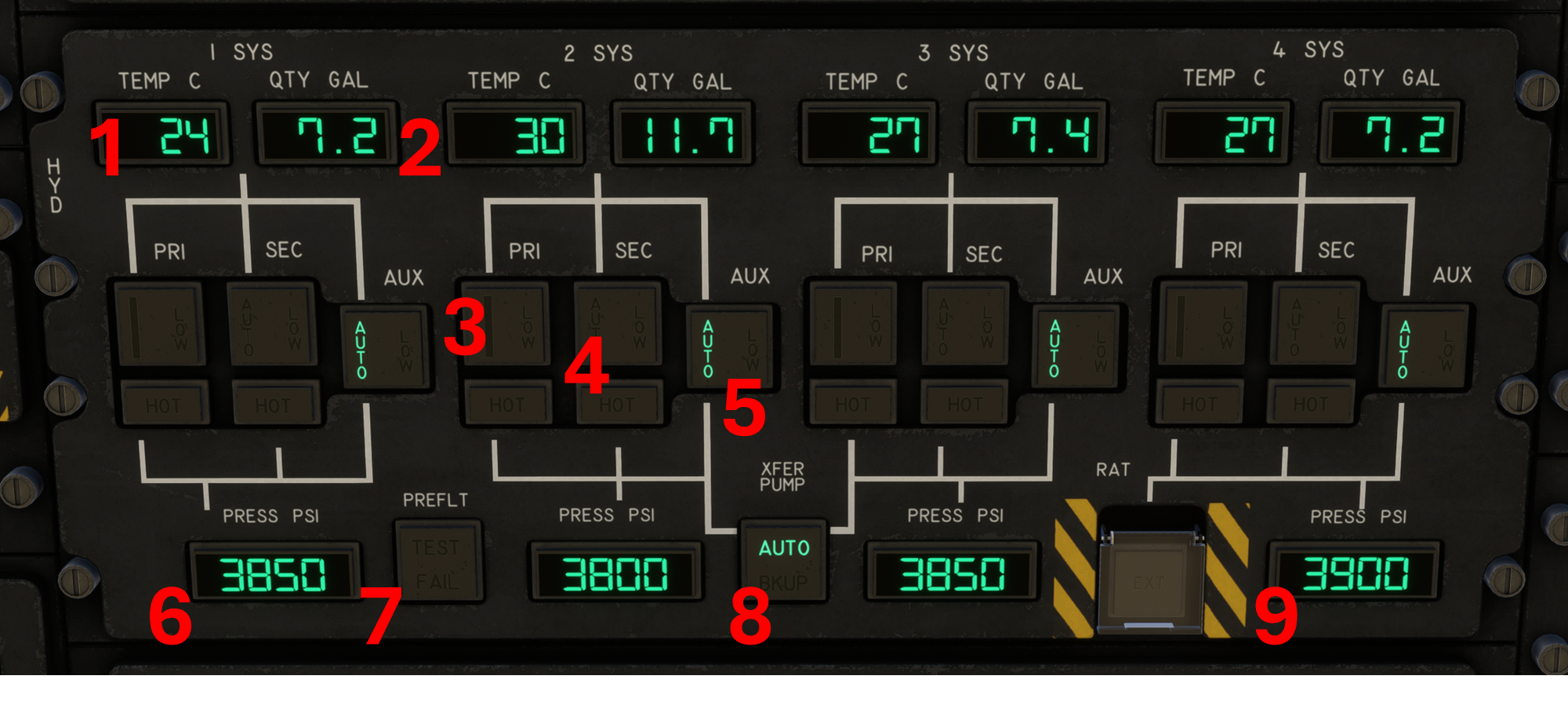
The Hydraulic panel is located on the overhead panel of the aircraft, right above to the fuel and engine panels.
Hydraulic System Panel
1. **Reservoir Temperature Display,** in degrees Celcius, for the associated system.
2. **Reservoir Quantity Display,** in gallons, for the associated system.
3. **Primary Engine Driven Pump (x4):** Provides on/off control of the associated pump.
4. **Secondary Engine Driven Pump (x4):** Provides on/off control of the associated pump.
5. **Auxiliary Driven Pump (x4):** Provides on/off control of the associated pump. Aux Pumps are electric.
6. **Pressure Display:** Provides hydraulic pressure for the associated system, rounded to the nearest 50 psi. Any pressure less than 100psi is reported as zero. Normal range is 3800 - 4100 PSI
7. **Preflight System Test:** INOP
8. **XFER Pump:** Transfer Hydraulic Press between systems 2 and 3.
9. **RAT Switch:** Ram Air Turbine deploy switch, INOP.
The hydraulic system may be pressurized by the auxiliary pumps using electric power from the APU or Ground Power. The APU or GPU can pressurize all four lines to aprox. 3800 PSI (slightly under their normal pressure of 4000 PSI) by using the AUX Hydraulic Pumps on any of the systems. This means that ramps and doors, as well as control surfaces, can be fully operated on AC Power alone.
---
# Agent Instructions
This documentation is published with GitBook. GitBook is the documentation platform designed so that both humans and AI agents can read, navigate, and reason over technical content effectively. Learn more at gitbook.com.
## Querying This Documentation
If you need additional information that is not directly available in this page, you can query the documentation by asking a question.
Perform an HTTP GET request on the following URL with the `ask` and `goal` query parameters:
```
GET https://docs.miltechsimulations.com/miltech-simulations-microsoft-c-17-globemaster-iii/the-aircraft/aircraft-systems/hydraulic-system.md?ask=&goal=
```
`ask` is the immediate question: it should be specific, self-contained, and written in natural language.
`goal` is what the user is ultimately trying to achieve, the reason they need the answer. Sharing it helps GitBook give you a better, more relevant answer. A goal is most helpful when it describes the outcome the user wants rather than restating the question. For example, with `ask=how do I create an API token`, a goal like `automate deployments from our CI pipeline` lets GitBook tailor the answer to that use case.
The response will contain a direct answer to the question and relevant excerpts and sources from the documentation.
Use this mechanism when the answer is not explicitly present in the current page, you need clarification or additional context, or you want to retrieve related documentation sections.