 DOCUMENTATION
Navigation Pages (NAV)
The NAV pages show and change the route that the INS steering computer flies. They are DATA, DPS (destination points), FIX, RPLAN (route planning) and INIT (INS initialization).
How navigation works in this aircraft - please read.
The U-2S has its own INS steering computer. It flies the ACTIVE destination point (DP) file: the flight director, the MILES / TTG read-outs, the map track and the autopilot NAV mode all follow it. The MSFS flight plan is not used for INS steering.
DP files are shared between the MFD, the UFCD and the BCDU - enter a route on any of them. Files: ACTIVE (the one flown), STORE 1-4 (spare routes, 99 points each; a route sent from the MSFS EFB lands in STORE 1 by itself), EMER (16 emergency fields) and BULL (10 bullseyes).
The INS must be in NAV. Without it the steering computer has no position and the autopilot refuses NAV mode.
How the steering computer flies each mode - F/T turns, direct steer, overfly, orbits and the T/T family - is explained on its own page: Navigation System (INS Steering).
DATA
The top block, STEERING DATA, shows and sets the steering. Press L2 EDIT and step through the mode, the DP / course / distance fields that belong to it, then ORB and OFLY. Steering values (mode, DPs, course, distance, orbits) are staged: the new value shows in reverse video and is only sent when you press R1 ENT.
In F/T a new TO DP sent this way is a direct steer from present position. Outside a staged edit, R1 BARO switches the INS altitude to the barometric loop (green while on).
Example MFD data
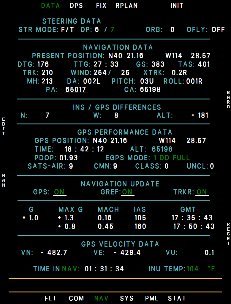
- Steering mode and DPs
- Present position
- Time to go
- INS/GPS differences
- EGPS mode
- Navigation update
- G-load log
- Time in NAV
- INU temperature
- EDIT (L2)
Next to the STEERING DATA heading the steering computer tells you, in magenta, when it is not flying your selection as entered: 128 MAX (intercept distance limited to 128 NM), 400 MAX (more than 400 NM out - direct steer instead), ZONE 1 / ZONE 5 (too close to the destination or to its inbound line - direct steer instead) or OVERSHOOT TURN (a turn of more than 140°).
The message stays while its condition holds and comes with the NAV STEERING advisory - see Navigation System.
- Navigation data: INS present position, distance and time to go to the turn point, ground speed, true airspeed (dashes without valid air data), track, heading, wind, cross-track, drift, pitch, roll and the INS altitude.
- INS/GPS differences: north/south and east/west in feet, and INS minus barometric altitude. A position difference turns cyan above 1,000 ft (2,000 ft in a bank of more than 5°); the check rests for 5 minutes after GPS aiding comes back. Dashes without a GPS solution.
- GPS performance: GPS position, time and altitude, PDOP, the satellite counts and the EGPS MODE - 1 DD FULL in normal use (3 AUTO FULL with GREF off), 7 FREE when the INS runs free inertial (GPS updating off or GPS failed), 0 NO EGPS while the receiver starts up (the first minute after INS power-on, and in standby).
- Navigation update: GPS, GREF and TRKR ON / OFF (EDIT). With GPS updating off the INS drifts - see Inertial Navigation System.
- G load: present, maximum and minimum G with the Mach, airspeed and time at which they occurred; R6 RESET restarts the log. GPS velocities north, east and up are below it.
- Footer: TIME IN ALN / IFA / NAV from the INS (INS MODE: STBY before an alignment starts), and INU TEMP (green, cyan from 115 °F, yellow from 125, red from 135; blank for the first 20 seconds after INS power-on).
L4 MAN opens the manual position update - see Inertial Navigation System / Manual Position Update.
DPS - Destination Points
Table of the selected DP file - ACTIVE, STORE1-4, EMER, BULL, TP - with name, position and turn radius (on TP the target's size). Twelve rows per page, 99 DPs per file (EMER 16, BULL 10, TP 10).
The EMER file is listed nearest first (SORT column). The bottom block shows the nearest emergency field (or the one you pick with DSPL) with bearing, range, time and fuel on arrival, and bullseye 1 (or the one you pick) with its range and your bearing from it. Positions are the INS position.
Example MFD dps
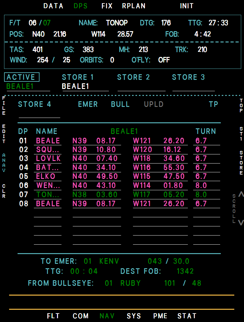
- Steer-to DP
- Selected file
- TO DP (green)
- Turn radius
- Nearest emergency field
- Bullseye
- FILE (L1)
- DS / ANAV (L3)
- STORE (R3)
- L1 FILE: next file (ACTIVE, STORE 1-4, EMER, BULL, UPLD while a datalink upload is pending, and TP, which is gray and skipped without an imaging sensor). R4/R5: scroll. R1 TOP: the page with the TO DP.
- L2 EDIT: L1/L2 pick the row, L3 steps LAT, LONG, TURN (DIA on the TP file), L5 EXIT. Type with the UFCD pad (latitude as DDMMmm, longitude as DDDMMmm) or use INC/DEC. R1 DEL blanks the row, R2 UNDO restores it. Names are entered on the UFCD or BCDU.
- On the ACTIVE file the TURN column shows a turn that does not fit between its DPs in yellow, with the smaller radius it is flown on. The file keeps your TR, and that is what EDIT shows on the row - see Navigation System.
- L4 CLR: L1/L2 pick a point, L4 ENT clears it, L5 EXIT. On a store, EMER, BULL or TP file R2 ALL clears the whole file (R1 YES).
- L5 DSPL (EMER and BULL files): L1/L2 pick which emergency field or bullseye the bottom block shows. L5 EXIT; on EMER the block then returns to the nearest field.
- With ACTIVE shown: R2 picks the store target ST1-ST4 and R3 STORE copies the route into it (R2 YES). With a store file shown: R2 LOAD copies it into ACTIVE (R1 YES, TO = DP 1).
- On the EMER and BULL files R2 IMPORT jumps to the LOAD page to fill them from SimBrief or the INS Planner; on the TP file it jumps to the TD file.
- TP file: the 10 targeting points, always all ten slots. DIA is the target's size in feet, entered with EDIT by pad (1 to 99,999) or INC/DEC (10 ft a step).
- Pending upload (UPLD file): L6 ACPT (choose the store with L4, then L5 YES) or L5 REJ (L4 YES). Uploaded points cannot be edited.
- L3 DS - direct steer (ACTIVE, EMER and TP files). On ACTIVE the TO DP number appears next to the right INC/DEC rocker: pick the DP with INC/DEC - any loaded DP, or 00, the position the INS was aligned at - and press R1 YES (R2 NO or DS again cancels).
On EMER a cursor starts on the nearest field: L1/L2 move it, R1 YES steers there and makes the EMER file the ACTIVE file. On TP a cursor starts on the first TP in use: L1/L2 move it, R1 YES steers there. While the autopilot flies the route in NAV, DS and LOAD read ANAV in cyan and do nothing - disengage NAV first.
Direct steer also works from the MAP page, NAV/DATA, the UFCD and (AVP off) the BCDU - see Navigation System.
FIX
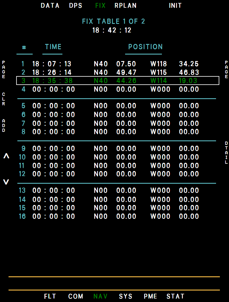
A log of up to 32 position fixes. A fix is recorded with L2 ADD on this page, the UFCD FIX key, the BCDU FIX key or NAV/DATA MAN → FIX, and automatically at every ALERT interval of the UFCD flight-time counter (default every hour, together with the ALERT TIME advisory).
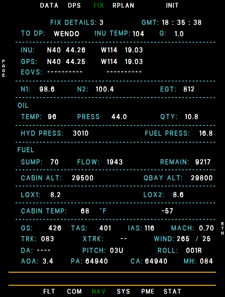
It appears on the table at once, and as a black X on the map. L3/L4 scroll, INC/DEC turns the page. R3 DTAIL opens a complete snapshot of the aircraft at that moment - engine, fuel, cabin, speeds, winds. The table is cleared at takeoff; when it holds 32 fixes no more are taken until you clear it with L1 CLR (L2 YES).
Example MFD fix
Example MFD fixdetail
RPLAN - Route Planning
Shows the active DP file as a flight log: leg distance, time and distance to go, ETA, and fuel remaining at each point, counted from the fuel totalizer (SYS/PERF TOTAL) and colored against your fuel bugs.
Example MFD rplan
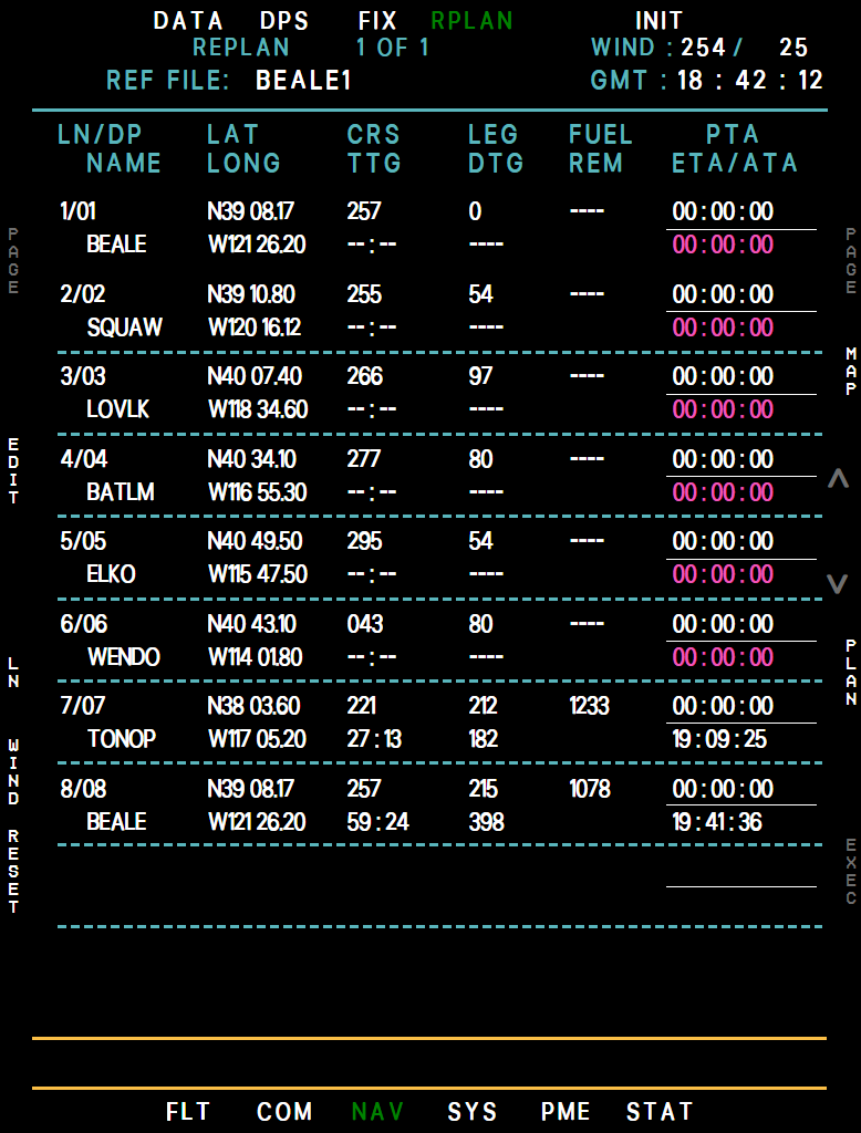
- Reference file
- Wind
- Passed DP (magenta)
- TO DP line
- Time to go
- Fuel remaining
- ETA
- EDIT (L2)
- WIND (L5)
- PLAN (R4)
- L5 WIND applies the current wind to the predictions (green while on).
- L2 EDIT enters a planned time of arrival (PTA) per point: L1/L2 pick the point, INC/DEC changes it by a minute, L3 EXIT.
- R1 MAP previews the route on the MAP page, in straight lines (green while previewing). R2/R3 or INC/DEC page through the lines.
- L4 LN highlights a line (L3/L4 move it). L5 ENT shows the predictions as if you flew from that line (cyan), L6 EXIT leaves.
- With a line highlighted, R6 EXEC then R6 YES hands the plan to the steering computer, which flies it: a direct steer from present position to that line's DP, then the lines in plan order - including reverse sequence, out-of-sequence points and direct-steer steps - to the last line. After the last line it steers direct to the next DP of the file, or starts the right turn if there is none. The executed start line is green, and the ACTIVE file itself is not changed.
- An executed replan ends when you make a new steering entry, load a new ACTIVE file or reach its end; the advisory RPLAN DISABLE then shows until the next EXEC. L6 RESET (L5 YES) withdraws an executed replan without that advisory and returns the plan to the ACTIVE file in sequence.
- R4 PLAN opens the plan builder: a list of steps, each SEQ (the file from a START to an END DP, up or down) or DS (a direct steer to a DP). L2 EDIT, L3 ADD, L4 DEL and L5 RESET build it, INC/DEC changes the boxed field, R2 ENT recalculates, R1 MAP previews and R6 RTN returns. The REPLAN lines then follow your plan.
INIT - INS Initialization
Example NAV INIT page
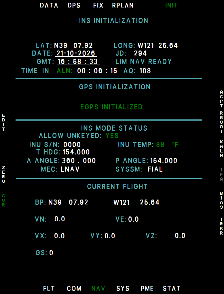
- Position: The alignment position you gave the INS (while in standby or aligning), otherwise the live INS position.
- Date and GMT
- Status: ENTER POS / LOAD, ACFT MOVED, LIM NAV READY or FULL NAV READY.
- Time in Mode and Align Quality (AQ): TIME IN ALN / IFA / NAV from the INS, or INS MODE: STBY before the alignment starts. AQ counts down from 300 during alignment - lower is better. During an in-flight alignment CHG HDG 45° appears in magenta next to AQ partway through: turn about 45°. The turn is optional - the alignment finishes on time either way - and the cue goes once you have turned 40° or more.
- INU Temperature
- ALN / ACPT (R1): ALN starts the ground alignment, confirm with R2 YES. When a READY state is reached the legend changes to ACPT - press it and confirm with R2 YES to go to NAV.
- IFA (R4): In-flight alignment, available in the air with the INS aligning or navigating. Confirm with R3 YES (R4 NO).
- EDIT (L2): Boxes the date, GMT and ALLOW UNKEYED fields. The date and time always follow the simulator clock, and in our rendition these entries have no effect. There is no position entry on this page - see below.
Example MFD init
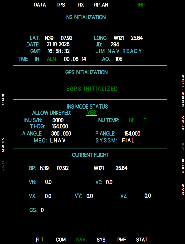
The INS gets its alignment position from the INS switch in LOAD. The MFD has no LAT/LONG entry: to type a position by hand, use the BCDU NAV INIT page, which is only available with the AVP off (BCDU backup control).
In the GPS INITIALIZATION block the EGPS line reads EGPS OFF, EGPS INITIALIZING ... or EGPS INITIALIZED; during the alignment MEC and SYSSM show its phase.
L5 CUR shows the INS position and velocities in the bottom block; R5 BIAS and R6 TRKR show reference data (display only). L4 ZERO, R2 RBOOT and R3 KALM ask for confirmation but do not change the navigation in our rendition. All legends are gray until the INS is powered. The full alignment procedure is in Inertial Navigation System (INS).