 DOCUMENTATION
Targeting Points
A targeting point (TP) is a spot on the ground you mark for the sensors: a building, a parked aircraft, a bridge. The aircraft holds up to 10 of them in one list, shared by all three MFDs. TPs act like destination points - they show on the MAP and on NAV/DPS, you can read their data, point a sensor at them and steer direct to them - but they are not a route: the steering computer never sequences through them.
TPs need an imaging sensor: the ASARS-2 nose, the SYERS-2A nose or the OBC in the Q-bay (EFB Aircraft tab). With the Standard nose and an empty Q-bay the TP and TD legends are gray and cannot be selected, and the MAP draws any TPs in gray. The list stays, so the TPs come back when a sensor is fitted. It lasts for the flight; ZEROIZE erases it.
Filling the List
| Way in | Where | What it does |
|---|---|---|
| TD file | STAT → LOAD | Replaces the whole list with the points of an INS Planner plan. |
| Designate | The sensor, and your Condition lever high idle binding | Puts the point the sensor is aimed at in the first free slot. |
| By hand | NAV → DPS, file TP | Type a position into a free slot, or correct a TP. |
Loading a TD File
TD (target data) is the STAT → LOAD file that fills the TP list from an INS Planner plan.
- MFD B6 STAT, T5 LOAD.
- L6 TD - INSPLANNER, and type the six-digit plan number into the ID box.
- R6 LOAD. The status reads LOADED, or LOAD FAILED with the reason.
R5 DTAIL opens the file's own page, where L3 FTCH fetches the points so you can look at them before you load. With the TP file shown on NAV/DPS, R2 IMPORT opens that page directly (L2 PLAN selects the ID box) and R7 RTN takes you back to NAV/DPS.
The load replaces all ten slots with the first 10 points of the plan. It takes the plan's target list; a plan without one gives its route markers instead. The INS Planner has no separate target type yet, so in practice any marker plan works.
Each point brings its position, its name (up to 8 characters; without one it is called TP01, TP02 ...) and, if the plan gives it, its size: a diameter, or a length and width with a heading. With no size it gets the default 300 ft.
Designating with a Sensor
Bind Condition lever high idle in MSFS Controls (see Keybinds Guide). One press puts a new TP in the first free slot, at the point the sensor is aimed at. It is named after its slot, TP01 to TP10.
| Sensor | Where the TP goes | Its size |
|---|---|---|
| Camera open (SYERS-2A or OBC, CAM picture up, inside the gimbal stops) | The ground under the crosshair | Read from the object, else 300 ft |
| Radar operating, SPOT | The center of the patch | Read from the object, else 300 ft |
| Radar operating, SRCH | The cursor | Always 300 ft - the picture is too coarse to read |
The object read. After a camera or SPOT designate the TP appears at once as a 300 ft square. Within a few seconds, if something can be read there, it moves onto the center of the object and takes the object's length, width and heading. The read looks for, in this order:
- A parked aircraft near the point, about 130 × 120 ft along its heading. SPOT only, with the RDR page up on the left MFD, and only live traffic counts.
- The OpenStreetMap building the point lies in: the smallest rectangle around it.
- The object the camera's aerial imagery shows at the point: a shape that stands out from the ground around it, right at the crosshair. A parked C-130, for example, reads as about 115 × 100 ft.
Open ground, ground texture, anything that runs on like a road, anything very small and a point with no connection to the map servers all keep the 300 ft square.
Seeing TPs
MAP. Every TP is a hollow yellow triangle with a dark casing, whatever the SMBL options. Its number (1 - 10) sits below it on the left; with ICAO on, its name sits on the right. There are no lines between TPs.
On AMP and RCTR, R2 steps through the files to TP. Pick the TP with the right rocker (it turns green) and press R1 ENT: AMP shows its position, bearing / range, time to go and fuel at the point, RCTR centers the map on it.
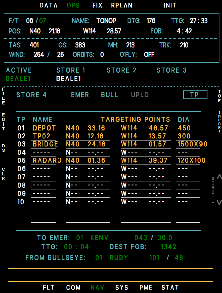
NAV/DPS. L1 FILE to TP, after BULL and UPLD. The table is headed TARGETING POINTS and always shows all ten slots: number, name, latitude, longitude and size, with dashes in a free slot.
- DIA is the size in feet: one number for a plain TP, length X width for a read object, such as 120X100.
- L2 EDIT: L1/L2 pick the row, L3 steps LAT, LONG, DIA, L5 EXIT. Type with the UFCD pad or use INC/DEC. DIA takes 1 to 99,999 ft by pad and moves 10 ft a step by INC/DEC; a read object's width scales with it. A position typed into a free slot makes a new TP of 300 ft. R1 DEL blanks the row, R2 UNDO restores it.
- L4 CLR: L1/L2 pick a TP, L4 ENT clears it, L5 EXIT. R2 ALL clears the whole list (R1 YES).
- Names come from the TD file. They cannot be typed in the cockpit: the UFCD and BCDU, where DP names are entered, have no TP file.
Example MFD NAV/DPS TP file
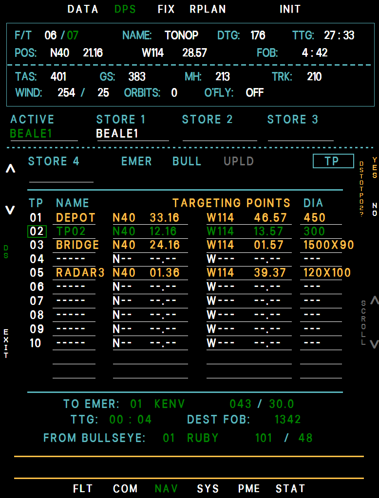
Example MFD NAV/DPS direct steer to a TP
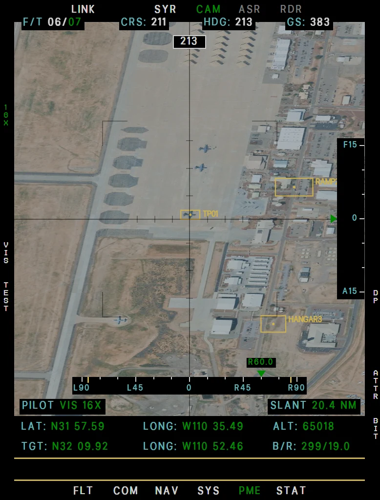
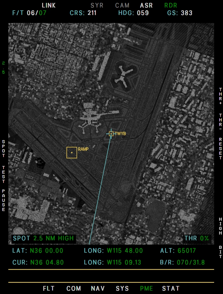
CAM and RDR pictures. Each TP in the picture is a flat yellow box, square to the picture, with a dot on the point and the name beside it. The box is the outline of the target's footprint on the ground at the picture's scale, so it tells you how big the target is:
- Radar. The footprint on the scope. In SRCH only TPs inside the fan are drawn; in SPOT those on the patch.
- SYERS-2A. The footprint as the camera sees it. Straight down it has its true shape. The further out you look the flatter it gets - about 3.6 : 1 at 40 NM from 65,000 ft - and it grows as you zoom in.
- OBC. The same, on the live feed, and on the held picture in PAUSE or at MAX FRAMES.
- A box too small to see is held at 14 pixels on its short side, keeping its shape up to 6 : 1.
Example MFD CAM page with TP boxes
Example MFD RDR page with TP boxes
Pointing a sensor at a TP. TP is a file in the DP select of both sensor pages:
- CAM (camera open): R4 DP, R2 until it reads TP, pick the TP with the right rocker, R1 ENT. The camera slews to it and locks on it. Every TP is offered: a number in amber is out of reach (85° to the side and 15° fore / aft, 45° to the side for the OBC) and ENT does nothing until it comes into reach. R4 again, or moving the hand control, ends the slew.
- RDR (SRCH, radar operating): R4 DP, R2 until it reads TP, step through the TPs in the fan with the right rocker (the picked box is heavier), R1 ENT. The cursor follows the TP; L3 SPOT then images it. Moving the hand control ends it.
Direct Steer to a TP
- NAV → DPS, L1 FILE to TP.
- L3 DS. A cursor starts on the first TP in use; L1/L2 move it.
- R1 YES beside DS TO TP02?. R2 NO, L5 EXIT or DS again cancels.
The aircraft flies a normal direct steer straight to the TP, with a magenta line on the map from where it began. On arrival it goes into a continuous right turn at 15° of bank; if it passes more than 1.45 NM from the TP it steers back to it first.
The turn is not tracked, so wind drifts it, and it never goes on to a DP: it stays in that turn until you make another steering selection.
The TP is not in the ACTIVE file, so the steering shows TO DP 00, on the UFCD and BCDU too. Only the top block of NAV/DPS shows the TP's name. The direct steer works from NAV/DPS only, with the INS in NAV.
While the autopilot flies the route in NAV the key reads ANAV and does nothing - disengage NAV first. It is not available while EMER is the active file.
Advisories
| Message | Why | What to do |
|---|---|---|
| TP LIST FULL | All 10 slots are in use. It stays on until one is free. | Clear a TP on NAV/DPS before the next designate. |
| TP DESIGNATE FAILED | For 5 seconds after a designate that found no free slot, or no sensor aimed at the ground. | Open the camera (or leave TEST) with the ground in view, or get the radar operating - airborne with MK IV MODE 1-5. If the list is full, clear a TP. |