 DOCUMENTATION
Standby Flight Display (SFD)
The Standby Flight Display (SFD) is a small self-contained instrument that keeps working when everything else is dark. It has its own power switch and runs from the emergency DC bus, independent of the AVP and the MFDs.
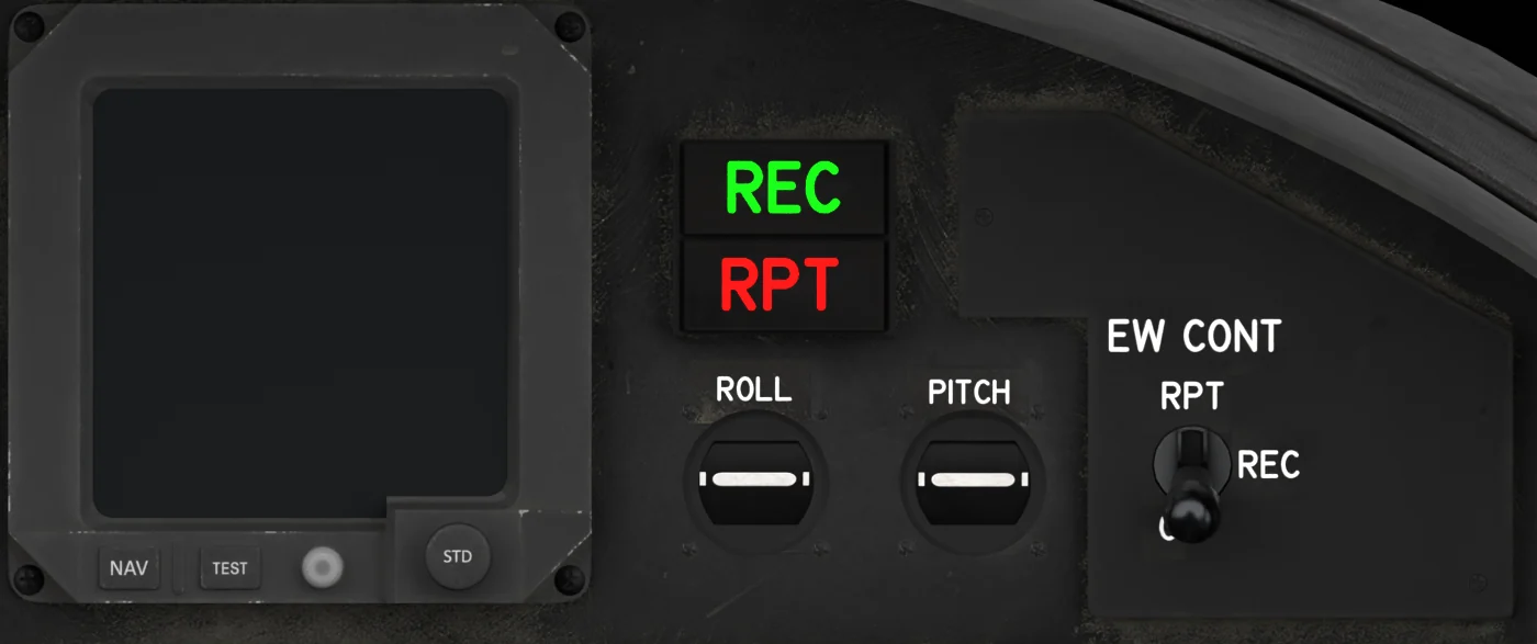
- EW REC - Lit while the EW system tracks a red threat: sim traffic within 5 NM and 1,000 ft of you, moving faster than 20 kt.
- SFD - Standby flight display: own attitude sensors, airspeed, altitude, heading and Mach, and its own baro knob. Runs on emergency DC, independent of the MFDs.
- EW RPT - Flashes while EW CONT in RPT is jamming a red threat; REC stays lit with it.
- ROLL SYNC - Shows the load on the autopilot roll servo; centred with the autopilot off. Off centre in cruise points to a heavy wing.
- PITCH SYNC - Shows the load on the autopilot pitch servo; centred with the autopilot off. Off centre with PITCH TRIM in MANUAL: trim until it centres.
- EW CONT - OFF / REC / RPT. REC detects threats (sim traffic stands in for them); RPT adds jamming. A startup self-test runs first (tooltip REC - SBIT). While it is OFF (or unpowered) with the AVP up, EW NO RESPONSE shows. The STAT/FAULT EW BIT takes about 30 seconds (EWS IBIT IN PROGRESS on the EW page).
- SFD NAV - Cycles OFF / ILS / BC: localizer and glideslope bars from NAV 1. Together with TEST it starts the SFD built-in test.
- SFD TEST - Built-in test below 60 kt: hold NAV (mouse: click NAV), then press TEST twice within 2 s. On its own it does nothing.
What It Shows
- Attitude ball with pitch ladder and roll pointer.
- Airspeed tape (left, from 60 knots - the higher speeds are at the bottom), altitude tape (right), heading tape.
- Mach number top-left (M.720, shown from Mach 0.30 - blank below) and barometric setting top-right (29.92 IN or STD; while the PFDs are switched to hPa, the SFD's own setting in hPa, without a unit - for example 1013).
- A red band on the speed tape marking your current maximum speed (see below), and with the EFB option Stall speed tape on a yellow band up to the stall speed.
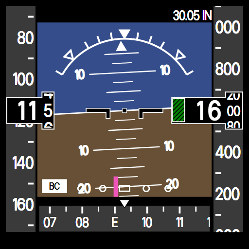
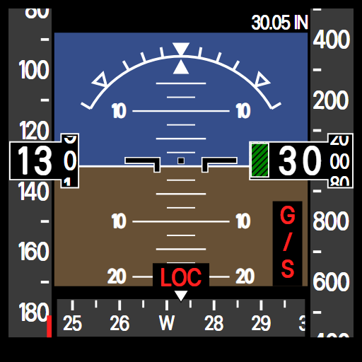
- ILS bars from NAV 1, chosen with the NAV button: ILS shows the localizer and glideslope bars, BC the localizer bar only. With no signal, red LOC and G/S flags take their place. The glideslope bar runs behind the altitude readout box, so on the glidepath (within about 0.2°) you will not see it.
- Below 10,000 ft a green hatched box takes the place of the ten-thousands digit of the altitude readout.
Example SFD flight
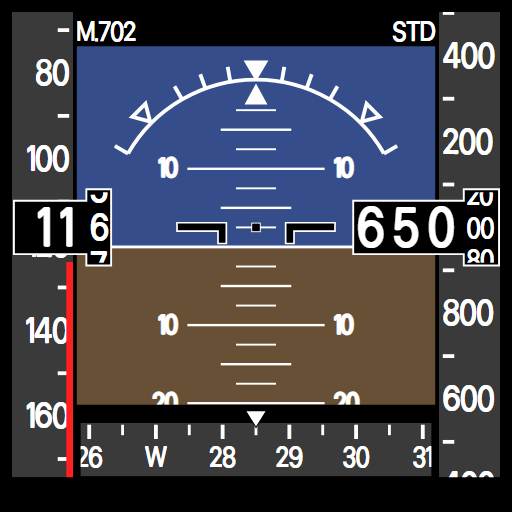
- Mach number
- Baro setting (STD)
- Airspeed tape
- Airspeed readout
- Red max-speed band
- Altitude tape
- Altitude readout
- Pitch ladder
- Roll pointer
- Heading tape
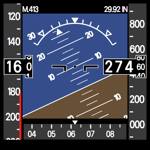
Example SFD climb
Power-Up
- Battery on, then SFD switch (right console) ON.
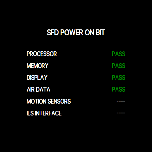
- A 6-second power-on test runs: white screen, color bars, grid, then an SFD POWER ON BIT list.
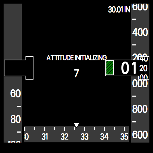
- The attitude area then turns sky blue with the roll scale and the aircraft symbol, but no horizon or pitch ladder yet: ATTITUDE INITIALIZING inside the roll scale and the seconds left under the symbol (10 SECS), for 10 seconds (or 180 seconds with the EFB option Avionics startup time on Realistic). Speed, altitude and heading are usable straight away.
- Do not move the aircraft. Any movement restarts the count - also after takeoff, where it would never finish (see below).
Example SFD powerup bars

Example SFD powerup grid
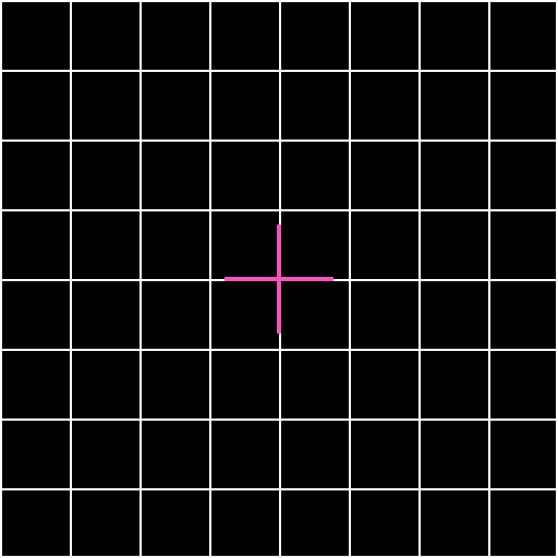
Example SFD powerup
Example SFD align
The SFD has its own motion sensors, so its attitude depends only on SFD power and its own initialization - it does not need the INS. What happens after a power interruption depends on how long it lasted and whether you are flying (60 knots or more, or airborne):
| Power off for | On the ground | In flight |
|---|---|---|
| Up to 5 seconds | The screen blanks for a second. Nothing is lost. | |
| 5 seconds to 2 minutes | Blank for 5 seconds (Realistic: 1 minute), then the attitude comes back with an error of 7 to 10° in pitch, roll or both. The error stays until the next full initialization - run the IBIT (below) to get one. If the initialization had not finished, it simply starts again. | Blank for 5 seconds (Realistic: 1 minute), then normal data. |
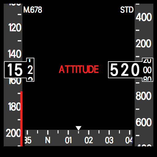
| More than 2 minutes | A full start-up: power-on test, then the attitude initialization. | Blank, then an airborne alignment of 10 seconds (Realistic: 3 minutes) under a red ATTITUDE flag. Heading, airspeed and altitude come back with the screen. |
Example SFD airalign
An initialization still running when you start to roll never finishes. Switch the SFD off and on again once you are flying (60 knots or more) and it becomes an airborne alignment instead. If your flight starts with the engine running (runway or air start), or after an EFB Set up aircraft preset, the SFD is ready immediately.
Controls
| Control | Function |
|---|---|
| Baro knob - turn | Altimeter setting, 0.01 inHg per click - or 1 hPa per click while the PFDs show hPa (PFD BARO, R4). The SFD has its own altimeter setting, separate from the PFD, and its altitude follows it (about 1,000 ft per inch) - set both. |
| Baro knob - push | Standard pressure (29.92 inHg / 1013 hPa, shown as STD) in either unit. Turn the knob to leave STD. |
| NAV button | Cycles OFF → ILS → BC (back course) → OFF. Shows localizer and glideslope bars from NAV 1 (BC: the localizer bar only; red LOC and G/S flags without a signal). After any power loss it starts again in OFF. |
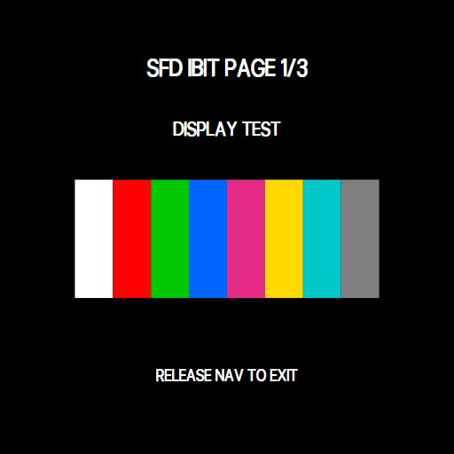
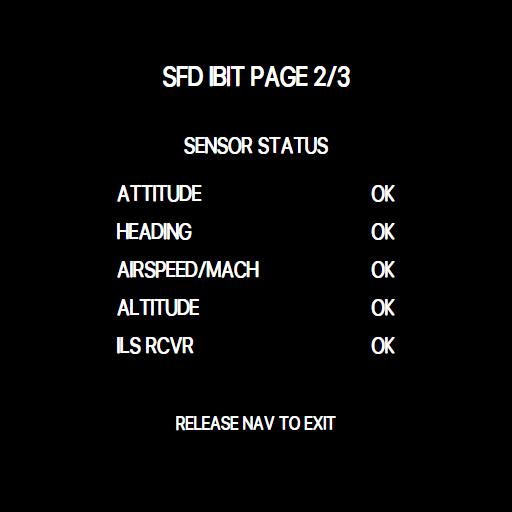
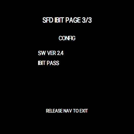
| TEST button | Built-in test (IBIT), below 60 knots once the SFD has finished starting: hold NAV and press TEST twice within 2 seconds. With the mouse, click NAV, then click TEST twice straight after. The three IBIT pages - display test, sensor status and configuration with IBIT PASS or IBIT FAIL - change by themselves every 3 seconds. Release NAV (with the mouse: click NAV again) to leave. The SFD then runs its power-on test and a new attitude initialization (10 seconds, Realistic: 3 minutes), so keep the aircraft still. TEST on its own does nothing. |
Example SFD approach
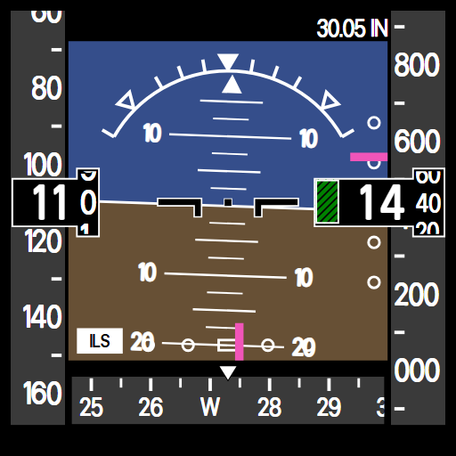
Example SFD nav bc
Example SFD nav noils
Example SFD ibit1
Example SFD ibit2
Example SFD ibit3
The Red Max-Speed Band
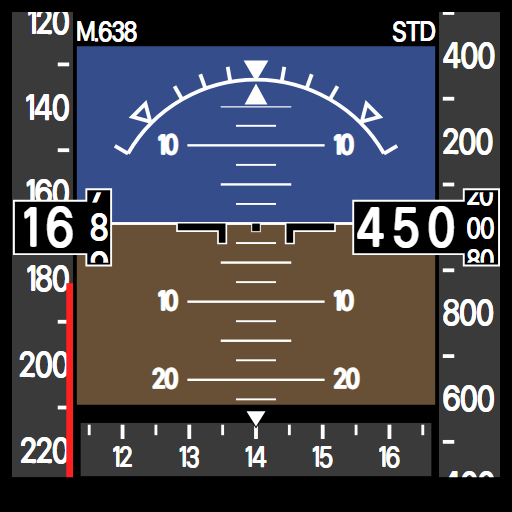
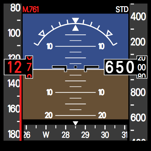
The U-2's speed limit changes with altitude and with the gust-control setting. The red band always starts at your current limit, and the speed readout turns red when you exceed it. The PFD uses the same limits. The SFD works its band and its red Mach limit out from its own altitude, so they follow the SFD baro setting.
Example SFD maxspeed
Example SFD overspeed
| Altitude | Airspeed limit | Mach limit |
|---|---|---|
| Below 30,500 ft | 181 KIAS (wing faired) 241 KIAS (gust control UP, once both the flaps and the ailerons are up) |
M 0.75 |
| 30,500 - 43,000 ft | M 0.65 | |
| 43,000 - 49,500 ft | 181 KIAS | M 0.75 |
| Above 49,500 ft | - |
The lower of the two limits applies.