 DOCUMENTATION
Electrical and Avionics Power
The U-2 electrical system provides and distributes power to the avionics, displays, fuel pumps, flight control systems and lighting. You do not need to understand it to fly the aircraft - leave everything in NORM and it manages itself. This page is for when a lamp comes on and you want to know why.
The electrical system consists of:
- A Main AC Generator and a Main DC Generator, both driven by the engine.
- A Standby AC Generator, driven by hydraulic pressure.
- A Battery, a Transformer-Rectifier (TR) and an Emergency Inverter.
- A connecting port for a Ground Power Unit.
Where the Power Comes from
| Source | Available | Feeds |
|---|---|---|
| Battery | Always | Essential and emergency DC equipment - which includes the MFD screens. In our rendition the AVP and UFCD also run on battery alone, so every display can be started without ground power. There are two batteries: the utility battery carries the buses first and the emergency battery takes over in flight when it is nearly flat. Together they last about 45 minutes, about 83 with ESS DC SHED pressed. |
| External power | On the ground, parked, with the ground power unit connected on the EFB Ground tab | Everything |
| Main AC generator | Engine running | All AC equipment (autopilot, EW system) |
| Main DC generator | Engine running | All DC equipment |
| Standby AC generator | Automatic if the main AC generator fails. Driven by hydraulic pressure. It keeps the essential AC load when the main generator comes back: move STANDBY GENERATOR to OFF for a moment to hand the load back. | Essential AC - keeps your autopilot and the EW system alive |
| Transformer-rectifier (TR) | Automatic if the DC generator fails | Makes DC from AC |
| Emergency inverter | Automatic if essential AC is lost | Emergency AC from the battery |
Switch-overs are automatic and take a little over half a second, so a display may blink when a source changes.
Electrical Switches
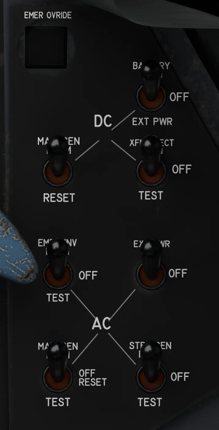
- BATTERY - NORM / OFF / EXT PWR. NORM for flight. EXT PWR runs the DC buses straight from the ground cart and rests the battery.
- MAIN DC GENERATOR - NORM / OFF / RESET. Engine-driven DC generator; in NORM after engine start it takes over the DC buses.
- TRANSFORMER RECTIFIER - NORM / OFF / TEST. Makes DC from AC, automatically if the DC generator fails. TEST gives TR ON.
- EMERGENCY INVERTER - NORM / OFF / TEST. Makes emergency AC from the battery automatically if essential AC is lost. TEST gives EMER INVERTER ON.
- EXTERNAL POWER - ON / OFF. Connects the ground power unit, AC and DC. It works only after the cart is connected on the EFB Ground tab (Servicing, Ground power: Connect), and drops off when the aircraft is no longer parked with the brake set.
- MAIN AC GENERATOR - NORM / OFF-RESET / TEST. Engine-driven main AC generator. It will not connect while external power holds the bus, and external power will not take over from a running generator. TEST checks it without connecting.
- STANDBY GENERATOR - NORM / OFF / TEST. Hydraulically driven; takes over essential AC if the main AC generator fails. Needs 2,500 psi hydraulic pressure.
The cockpit has no voltmeter; the electrical state is shown by the warning lamps and, on the U-2S, by MFD alerts.
Ground power comes from the cart on your stand. The ground power unit on the EFB Ground tab is the only source of external power - the MSFS ground-services power cart is not used. On a parking start it stands beside the aircraft by itself; otherwise set it to Shown.
Connect it under Servicing, Ground power: it drives to its service point and power is available once the cable is on. Then switch EXTERNAL POWER ON. It needs the aircraft stopped off the runway with the parking brake set or the wheel chocks fitted and the cart within 35 m.
Releasing the brake, hiding the cart or moving it further away disconnects it within a second - with BATTERY still in EXT PWR that leaves the DC buses dead, so put MAIN DC GENERATOR or BATTERY in NORM first.
Avionics Power Switches (Right Console)
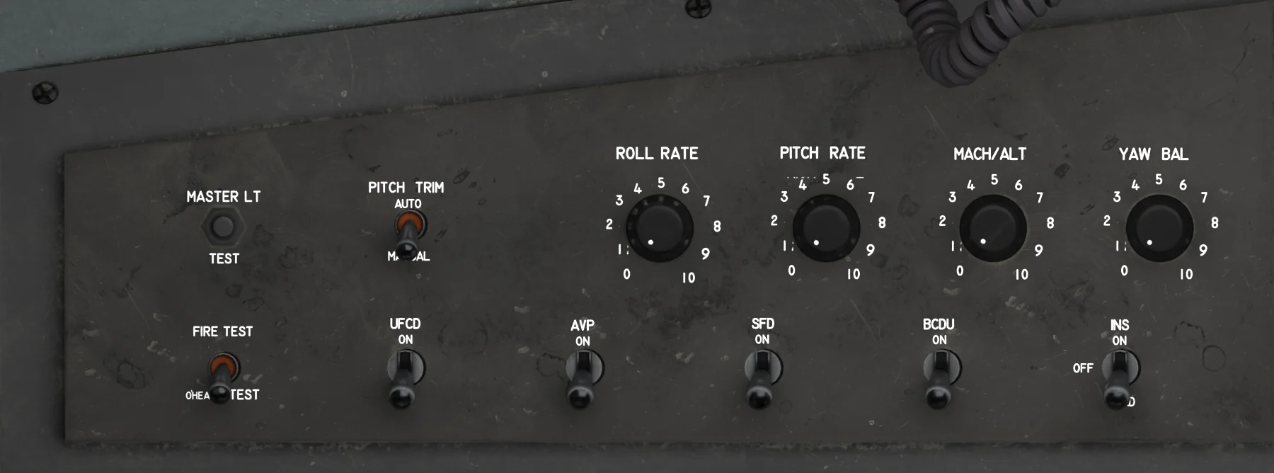
- MASTER LIGHT TEST - Lamp test: every warning lamp, MASTER CAUTION, the AOA indexer, AFCS and EW lamps. See Warnings and Alerts.
- PITCH TRIM MODE - AUTO / MANUAL. Autopilot auto-trim. See AFCS System.
- ROLL RATE - Autopilot roll gain, 0-10. See AFCS System.
- PITCH RATE - Autopilot pitch gain, 0-10. See AFCS System.
- MACH/ALT - Autopilot MACH and ALT hold gain, 0-10. See AFCS System.
- YAW BAL - Autopilot rudder trim. See AFCS System.
- FIRE/OHEAT TEST - FIRE TEST / OFF / OHEAT TEST. Tests the FIRE, BLEED and OVERHEAT lamps. Return it to the center.
- UFCD - ON / OFF. Up-front control display: 9 s self-test, then NO COM until the AVP is up.
- AVP - ON / OFF. Avionics processor behind all three MFDs; up after 7 s (Realistic 2 min). Until then the MFDs show DISPLAY BUS OR AVP FAILURE.
- SFD - ON / OFF. Standby flight display: 6 s power-on test, then 10 s attitude initialization (Realistic 3 min). Keep the aircraft still.
- BCDU - ON / OFF. Backup control display unit: INS alignment, destination points and steering while the AVP is off. About 15 s to start.
- INS - ON / OFF / LOAD. ON powers the INS in standby. LOAD springs back to OFF after loading present position and date; then select ON.
The start-up times follow the EFB option Avionics startup time (Fast / Realistic). Each MFD also has its own OFF / NIGHT / DAY knob: from OFF it runs a 9-second power-on test.
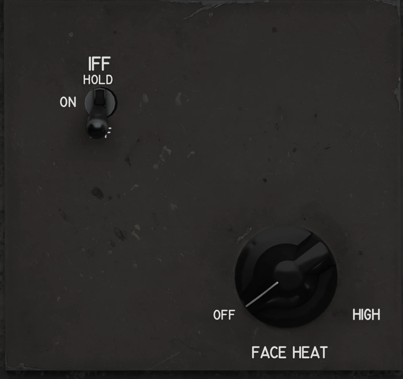
- IFF - OFF / ON / HOLD. Transponder power, up in standby. HOLD springs back to ON; OFF within 15 s keeps the codes, direct OFF zeroizes Mode 4: Mode 4 on again then lights the IFF lamp, with IFF MODE 4 RPLY FAIL on the alert line.
- FACE HEAT - OFF / HIGH. There is no faceplate in the sim; the knob switches the windshield de-ice instead.
The IFF HOLD position keeps the stored codes when you switch the IFF off. It is spring-loaded: the switch returns to ON after 1 second, and the HOLD is remembered for 15 seconds, so select OFF within that time. Switching straight to OFF clears the secure-mode codes.